English
 Français
 Türkçe
 Español
 Русский

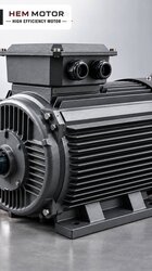
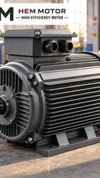
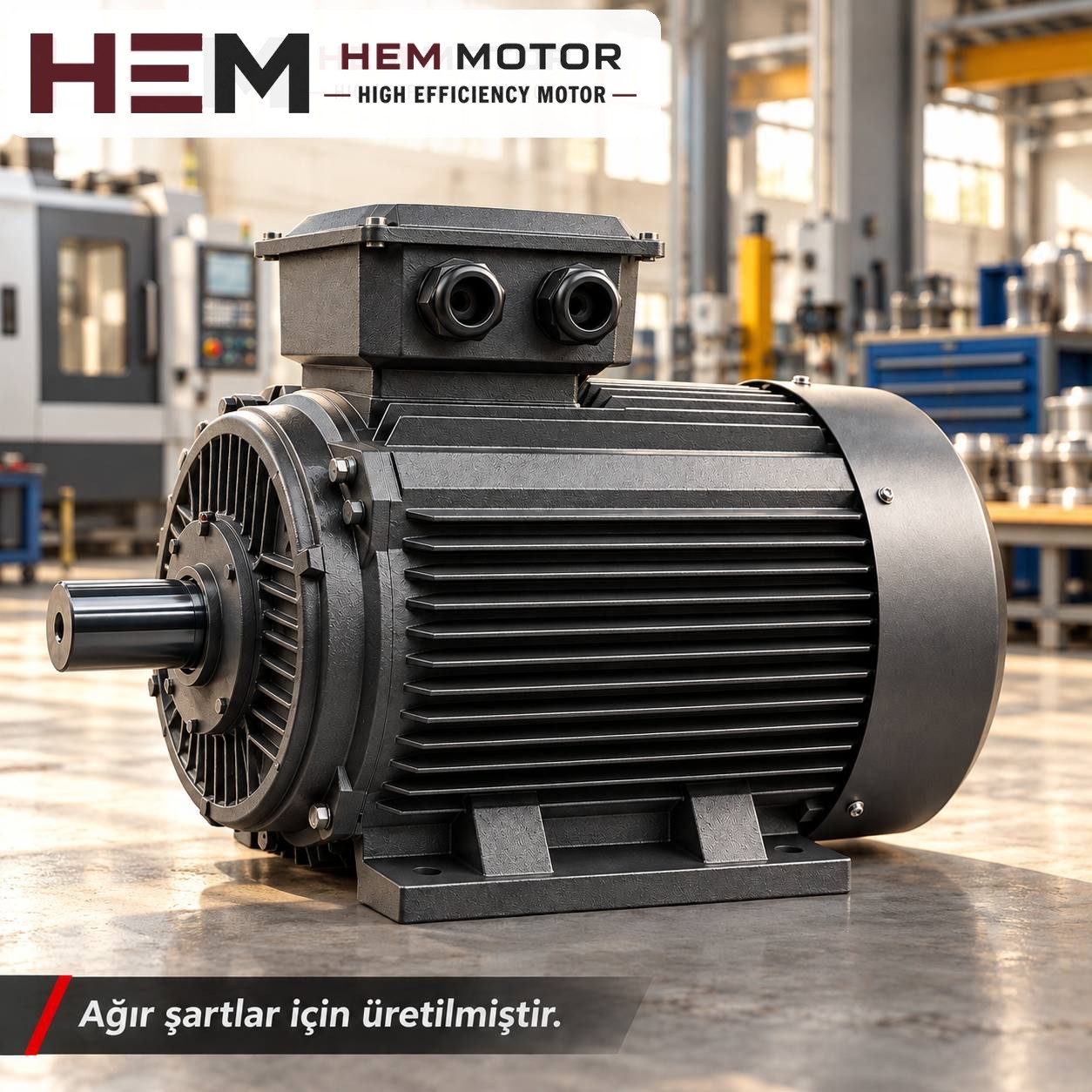

When a stenter fan motor is replaced, two conditions are decisive: the temperature where the motor sits must be at a level a standard IP55, class F motor can work in, and the new motor must turn at the same speed as the old one. The fan works inside the chamber, in hot air; the motor stands outside on the chamber roof or side. If these two conditions are not met, a more powerful motor will not solve the problem.
A stenter is a multi-chamber machine that holds fabric to width, dries it and heat-sets it. Each chamber has one or two circulation fans, and there is an exhaust fan at the end of the line. So a single machine may have dozens of identical fan motors; this makes standardisation easier during replacement, but it also carries any mistake into all the chambers.

Where does the motor sit on a chamber fan, and where does the shaft pass?
On most stenters the fan motor is placed vertically on the chamber roof; the shaft passes through the insulated roof and the impeller pushes hot air into the upper and lower nozzle boxes. In some designs the motor stands horizontally on the side wall. Before replacement, the most important question is this: is the impeller fitted directly on the motor shaft, or is there a separate intermediate shaft with its own bearings?
- Intermediate shaft design: The motor only turns the intermediate shaft through a coupling. A standard motor is more likely to fit this kind of design; matching frame, flange and shaft-end dimensions is enough.
- Impeller directly on the motor shaft: The shaft is long enough to pass through the insulation layer. If a standard motor's shaft length does not cover this length, the task needs a special-shaft motor; such a motor may fall outside the standard range in HEM Motor's 2026 catalogue. Send us the old motor's nameplate and shaft dimensions.
Temperature on the motor side: which value should you report?
The process temperature inside the chamber is not the temperature of the motor. What must be reported is the temperature of the air around the motor frame. The stenter roof is heated by heat rising from the chamber and by heat from the burner or thermal oil heat exchanger. Take the measurement with the machine at full temperature, after several hours of running, at the point where the motor's fan cover draws in air.
If the measured value exceeds the operating conditions of a standard motor, the solution lies not in the motor itself but in the layout: ventilation above the roof, a heat shield, raising the motor slightly off the insulation surface and the like. The ambient temperature is stated in the order; if the value is uncertain, a measurement is needed instead of writing "hot roof". As temperature rises, the margin for safely delivering the nameplate power shrinks; so a motor of the same power should not be expected to carry the same load on a hot roof as in a cool workshop.
Oily lint: the real factor spoiling cooling on a stenter
On a stenter, fibre shed from the fabric combines with vapour from finishing chemicals and spinning oils to form a sticky layer. This layer coats the grille of the motor's fan cover and the frame fins. When the fan cover is clogged, the motor's own fan cannot push enough air; the frame heats up and winding and bearing life shorten. Behind many stenter fan motor failures there is not insufficient power but dirty cooling paths.
- When replacing, check how dirty the old motor's fan cover and frame are; take photos.
- Choose a layout that does not block access to the new motor's fan cover; regular cleaning must be possible.
- If the chamber doors and the seals at the shaft passage are worn, renew them; leaking hot, oily air comes straight to the motor.
- Because the fabric enters wet, steam is dense in the first chambers; on motors in that zone, check the terminal box gasket against condensation.
For motors working in dirty, hot surroundings, a cast iron frame with the same electrical values is a more rigid option; an aluminium frame stands out for its lightness when mounted on the roof.
Speed condition: number of poles and inverter frequency
The power a fan draws changes roughly with the cube of speed. On a stenter this has two practical consequences:
| Change | Fan speed | Power drawn by the fan (approx.) |
|---|---|---|
| Reducing frequency from 50 Hz to 45 Hz | 90% | 73% |
| Raising frequency from 50 Hz to 55 Hz | 110% | 133% |
| Fitting a 2-pole motor instead of a 4-pole one | about 2 times | about 8 times |
The values in the table are approximate ratios derived from the fan laws. As can be seen, even a small increase in frequency can push the motor above its nameplate power; changing the number of poles endangers both the motor and the impeller. When replacing, keep the old motor's number of poles, and if the chamber inverters are set to run above 50 Hz, assess the motor power accordingly.
On stenters, fan speed is usually adjusted chamber by chamber with a frequency inverter. Our three-phase ranges are suitable for speed control with a frequency inverter; according to the explanation in the inverter question, an external fan may be required for long periods of full-torque operation at low speed, a dv/dt or sine filter is considered if the drive-motor cable is long, and these conditions are stated with the order. Since fan load falls quickly at low speed, full-torque operation at low speed is rare for fans; however, it should not be forgotten that on a hot roof the motor's own fan pushes less air at low speed.
You can review current prices of HEM Motor models that may suit stenter fans on the buy electric motors page.