Booster Pump Electric Motor Replacement: Frequent Starts and Flange Compatibility

Booster Pump Electric Motor Replacement: Frequent Starts and Flange Compatibility

A booster set is a pump and tank arrangement that keeps the pressure in the water network of a building or plant within a fixed range. When a tap is opened the pressure drops and the pressure switch starts the pump; when the pressure reaches the upper value the pump stops. This simple operating logic can force the motor to start dozens or even hundreds of times a day. When a booster pump motor burns out or needs to be renewed, two issues come to the fore: whether the motor is operating in an arrangement suited to these frequent starts, and whether the new motor will fit the pump body exactly at the flange. This article covers both issues with steps that can be applied on site.

First identify the pump type: standard motor or special-shaft motor?

The pumps used in booster sets fall into different groups according to how they are connected to the motor. This distinction directly determines whether a replacement can be made with a standard motor.

  • Pumps working with a standard flanged motor: The pump has its own bearings and shaft, or the motor is connected to the pump adaptor with a standard IEC flange and shaft end. Most vertical multistage pumps and coupled horizontal pumps are in this group. In this case a standard three-phase motor can be used once flange and shaft compatibility has been confirmed.
  • Close-coupled (monobloc) pumps: The pump impeller is fitted directly onto the motor shaft, and the gland or mechanical seal runs on the motor shaft. On some of these pumps the motor shaft has a length, diameter or thread specific to the pump manufacturer. Such a motor is not equivalent to a standard motor; a special shaft is needed, and the replacement must be enquired about separately with the motor nameplate and pump information.

The easiest way to find out which group the pump belongs to is to look at the connection between pump and motor before removing the motor. If an adaptor and a coupling are visible in between, replacement with a standard motor is most probably possible. If the impeller casing is connected directly to the motor's front end shield with no coupling in between, it is a close-coupled design.
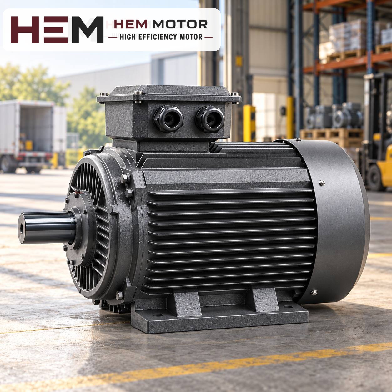
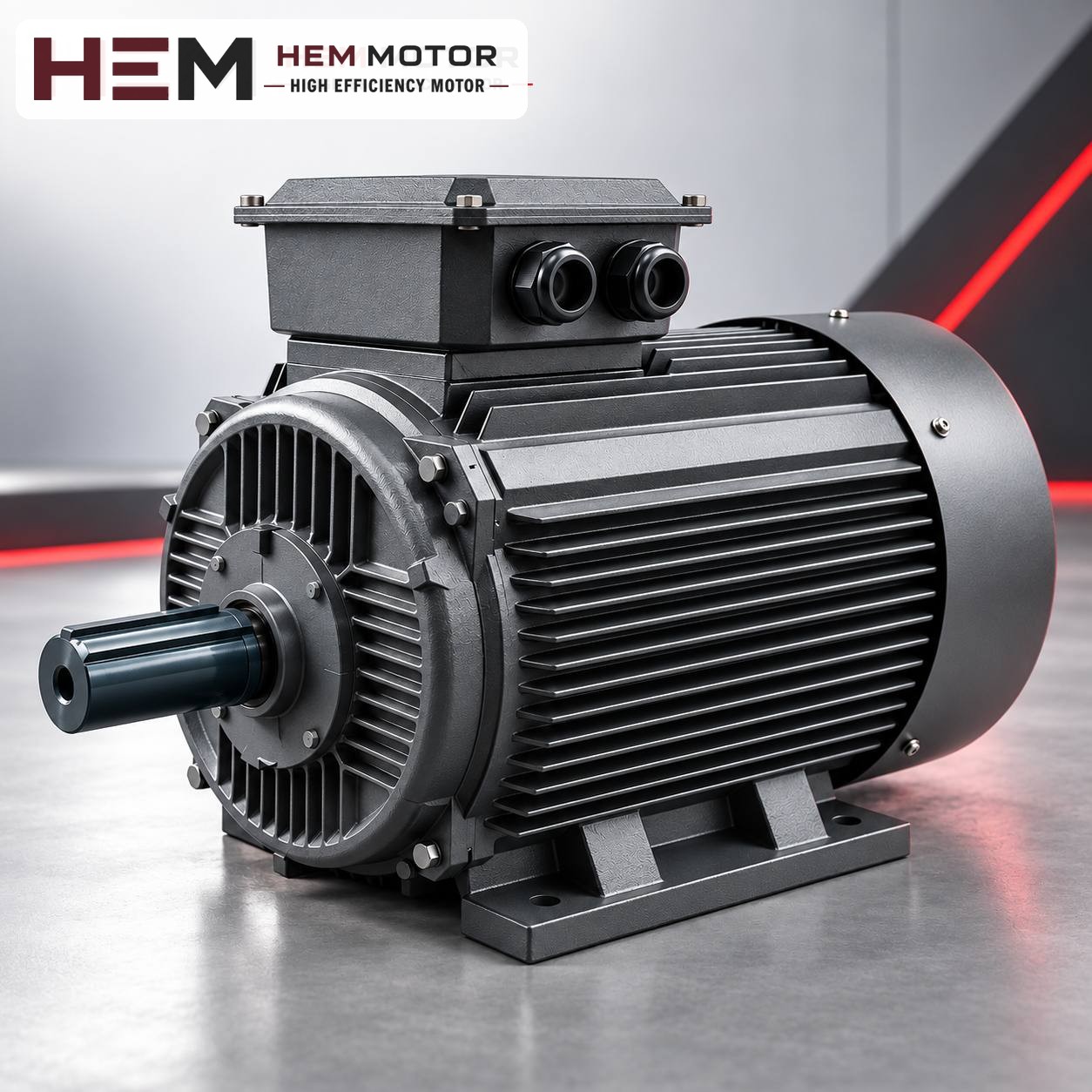
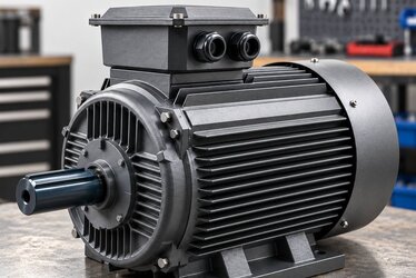
Three-phase electric motor in a workshop setting
On a pump motor, the flange type and shaft end are compared with the old motor before replacement (representative image).

How do frequent starts strain the motor?

When started direct-on-line, an asynchronous motor draws several times its rated current at the moment of starting. Even though this current lasts a very short time, it generates heat in the winding. If the motor does not run long enough, or stand still long enough, between two starts to dissipate this heat, its temperature rises a little more with every cycle. In booster sets this build-up often progresses unnoticed, and in the end the winding insulation ages.

Another effect of frequent starting is mechanical. With every start the coupling, shaft and bearings receive a sudden torque shock; the contacts of the pressure switch and the contactor also wear each time. For this reason the problem with a booster motor often stems not from the motor itself, but from how often the system starts it.

Common causes that increase the number of starts

  • Loss of tank pre-charge pressure: In a membrane tank the pressure on the air side decreases over time. The tank can no longer store water and the pump starts with every small draw-off.
  • Ruptured membrane: The tank fills completely with water and no longer acts as a buffer; the pump runs and stops at very short intervals.
  • Narrow pressure switch differential: If the lower and upper pressure values are very close to each other, the pump runs in short cycles.
  • Leaks in the system: A cistern or valve that leaks continuously makes the pump start at regular intervals, even at night.
  • Check valve failure: When the pump stops, water flows back, the pressure drops quickly and the pump starts again.

Checking these points before fitting the new motor prevents the same fault from recurring within a short time. If the motor has burned out and the tank pre-charge or membrane is faulty, the new motor will face similar conditions.

What measures can be considered for frequent starting?

The most effective way to solve the frequent starting problem is to reduce the number of starts on the system side. On the motor side, the following approaches are assessed:

  • Tank capacity and pre-charge: Setting the pre-charge correctly in relation to the lower value of the pressure switch and, if necessary, increasing the tank volume directly reduces the number of starts.
  • Setting the pressure differential: Leaving a reasonable range between lower and upper pressure allows the pump to run longer in each cycle.
  • Constant pressure control with a frequency inverter: Instead of stopping and starting the pump, the drive adjusts its speed to demand; the starting shock and the number of starts decrease noticeably. Our three-phase series are suitable for speed control with a frequency inverter; for long periods of full-torque operation at low speed an external fan may be required, and if the cable between drive and motor is long a dv/dt or sine filter is considered; these conditions are stated with the order. Details are in the question on inverter operation.
  • Correct thermal protection: The thermal relay must be set according to the rated current on the motor nameplate. A relay set higher does not protect the motor during frequent starts.

In a system with a high number of starts per hour, state the existing and planned operating pattern clearly in the order; the suitability of the motor for this condition is assessed together.

Prices and technical data are on the product pages; choose a model and order online.

Flange compatibility: do not rely on the names B5 and B14

On most booster pumps the motor is connected to the pump adaptor by its flange. Two basic flange types are found in this connection:

  • B5 (large flange, clearance holes): The flange has clearance holes, and the bolts pass through the flange into the adaptor.
  • B14 (small flange, tapped holes): The flange is close to the front end shield and the holes are threaded; the bolts are screwed into the motor flange from the adaptor side. This is common on vertical multistage pumps.

Even within the same IEC frame, there may be B14 flange variants of different sizes. This is why the information "B14 flange" is not sufficient on its own; the flange outer diameter, spigot diameter, bolt circle and number of holes must be compared with the old motor. The shaft diameter and shaft length must also match the coupling or impeller hub. These dimensions can be taken on site with a caliper and compared with the technical drawings; the 2026 technical and product catalogue also contains dimensions by frame.

Mounting arrangements are offered according to the frame: B3, B5, B14, B34, B35 and vertical V1/V3/V5/V6/V15 options are available; the flange size is confirmed with the order. On vertical multistage pumps the motor usually runs flange-mounted in a vertical shaft-down position; in this case the mounting position must be clearly stated in the order.

Example models: in power ratings common on booster sets

Booster pumps usually run with 2-pole motors, that is, with a synchronous speed of 3,000 rpm. The models below are examples; the power requirement of your pump is determined by the pump nameplate and the old motor nameplate.

Model codePowerPoles / rated speedIEC frameVoltageProduct page
90S-21.5 kW (2 HP)2 poles / 2,895 rpm90S230/400 V (Δ/Y), 50 HzAluminium 90S-2
90L-22.2 kW (3 HP)2 poles / 2,895 rpm90L230/400 V (Δ/Y), 50 HzAluminium 90L-2
100L-23 kW (4 HP)2 poles / 2,895 rpm100L230/400 V (Δ/Y), 50 HzCast iron 100L-2

These three models are rated 230/400 V (Δ/Y): on a 400 V three-phase network they are connected in star (Y). If the existing panel uses star-delta starting, it will not be compatible with these motors; in this case the panel arrangement must be stated in the order. All are IP55 with class F insulation. In closed, dry pump rooms the aluminium frame makes installation easier; in damp basements or pump rooms with splashing water a cast iron frame can be considered. The current price is on the product pages. Information specific to pump applications is on the pump electric motors page.

Hypothetical example: replacing the motor of an apartment booster set

The following sequence is hypothetical; it is not a real customer application. Suppose that the motor of a vertical multistage pump in the booster set in an apartment building's basement has burned out. The nameplate reads 2.2 kW, 2 poles and 230/400 V; the motor is connected to the pump with a B14 flange.

  • Confirm the pump type: An adaptor and a coupling are visible between motor and pump; replacement with a standard flanged motor is possible.
  • Keep power and speed: 2.2 kW and 2 poles point to the model with code 90L-2.
  • Measure the flange: The B14 flange outer diameter, spigot diameter, bolt circle and shaft dimensions of the old motor are taken and compared with the technical drawing; the flange size is confirmed with the order.
  • Find the cause of the starts: When the tank pre-charge is checked it turns out to be low; the pre-charge is adjusted and the pressure switch differential is reviewed.
  • Set the protection: The thermal relay is set according to the nameplate current of the new motor; the mounting position (vertical, shaft down) is stated in the order.

Conclusion and what to send before ordering

A successful booster pump motor replacement is achieved not only by finding a motor of the same power, but by eliminating the cause of frequent starting and matching the flange by measurement. Remember that a standard motor may not be suitable for close-coupled and special-shaft pumps. To determine the right model together, send us the following information:

  • Power, speed, voltage and a nameplate photo of the existing motor
  • Pump type (vertical multistage, horizontal, close-coupled) and the pump nameplate
  • Flange type (B5, B14) and dimensions, shaft diameter and length, mounting position
  • Starting method (direct-on-line, star-delta, drive) and estimated starting frequency
  • Ambient conditions in the pump room (humidity, splashing water)

Review suitable models and current prices on the buy electric motors page. To ask for the right model with your motor's nameplate data, send us a nameplate photo or contact us through our contact page.

HEM Motor Models Related to This Article

The cards show example models related to the topic. A suitable motor is not chosen by power alone: compare speed, voltage, mounting, shaft and connection dimensions on the product page; if unsure, send a photo of the existing motor’s nameplate on WhatsApp.

1.5 kW 3000 rpm Aluminium Frame Electric Motor 90S-2

90S-2

1.5 kW · 3000 rpm

  • Aluminium frame · IEC 90S
  • 2895 rpm · IP55
  • Mounting: B3 foot; flange (B5/B14/B35) depending on frame — confirmed with the order

US$113.25 (€101.07)

View product
2.2 kW 3000 rpm Aluminium Frame Electric Motor 90L-2

90L-2

2.2 kW · 3000 rpm

  • Aluminium frame · IEC 90L
  • 2895 rpm · IP55
  • Mounting: B3 foot; flange (B5/B14/B35) depending on frame — confirmed with the order

US$146.49 (€130.73)

View product
3 kW 3000 rpm Cast Iron Frame Electric Motor 100L-2

100L-2

3 kW · 3000 rpm

  • Cast iron frame · IEC 100L
  • 2895 rpm · IP55
  • Mounting: B3 foot; flange (B5/B14/B35) depending on frame — confirmed with the order

US$176.76 (€157.74)

View product

Similar Articles