English
 Français
 Türkçe
 Español
 Русский
 العربية

On some machines it is not enough to sit the motor on a base, nor to hang it from the machine housing alone. When the motor is long and heavy, and the pump or gearbox opposite it also needs a centred connection, two holding points are used together: the feet carry the load into the baseplate, while the flange seats the shaft on the axis of the driven machine. In IEC mounting codes this combined design is called B34 or B35. This page explains which job each design suits and what has to line up at the same time during installation.

When Should a Motor Be Fixed to Both the Base and the Machine?
On a flange-only motor, the whole weight and the vibration during operation reach the driven machine through the flange face and a few bolts. On small frames this is no problem. As the frame grows, the motor behaves like a long cantilever; the flange bolts, the cover of the driven machine and the bearings all have to carry this bending load.
When feet are added, the weight goes down into the baseplate and the flange is left with centring and torque transmission only. This arrangement is preferred especially in these cases:
- Drive groups in the medium and high power range where cast iron frame motors are bolted to a pump or gearbox housing,
- Packaged units where the motor and the machine sit on a common base and are transported together,
- Machines where shock or varying load makes a flange-only joint likely to work loose.
For comparison: B3 is a foot-only motor; the shaft is connected to the driven machine by a coupling or a belt and pulley, and centring depends entirely on alignment work. With B34/B35, the flange does the centring and the feet only provide support.
The Difference Between B34 and B35: Which Flange Is Fitted?
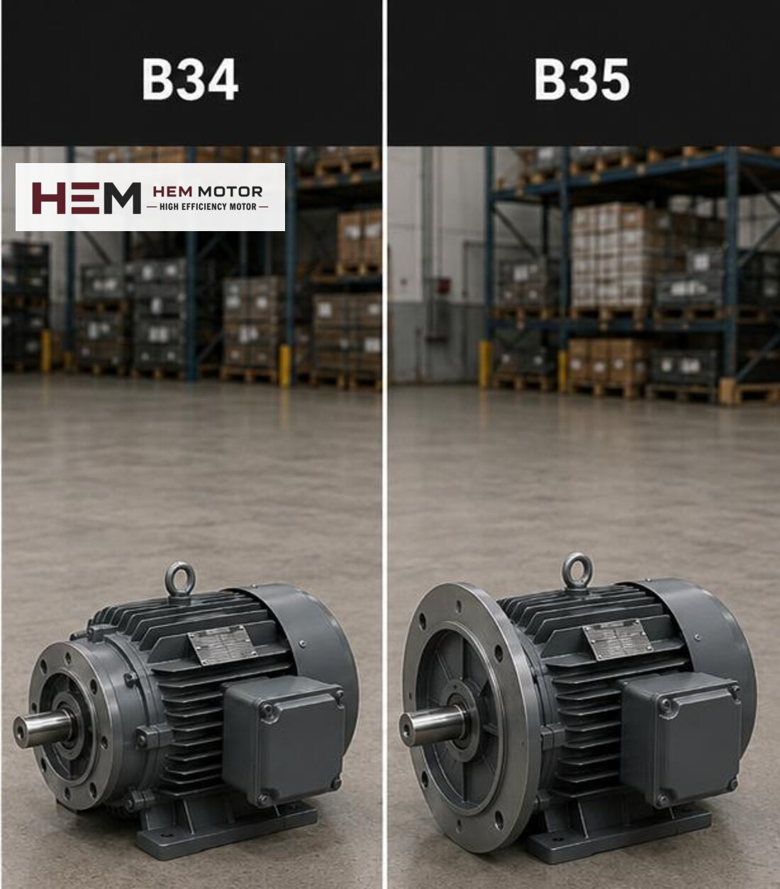
Both designs have the same feet; what sets them apart is the type of flange on the front end shield.
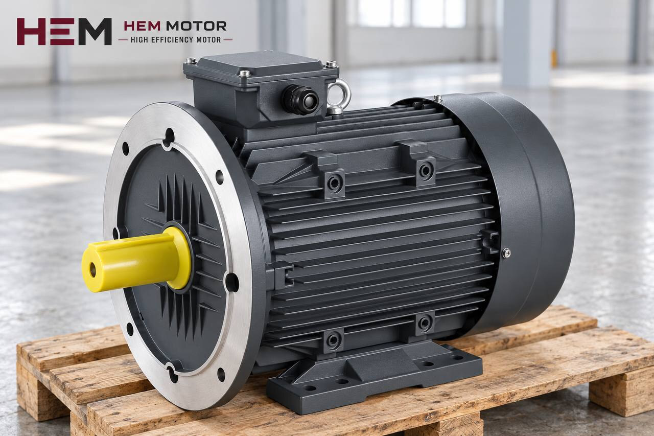
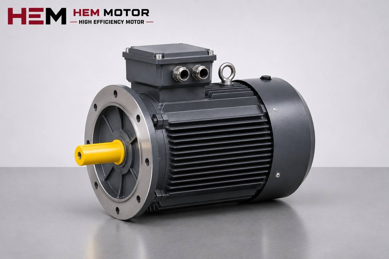
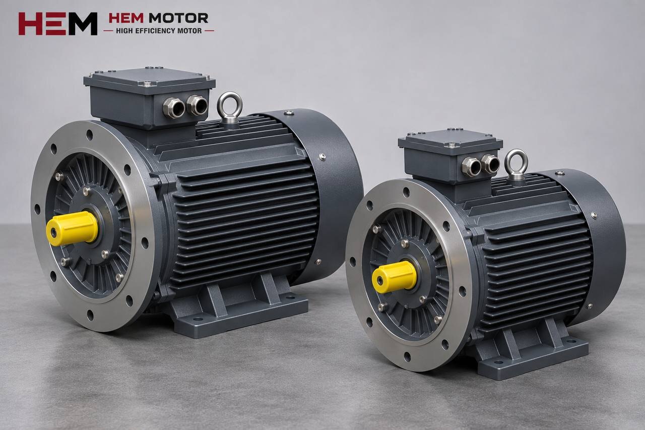
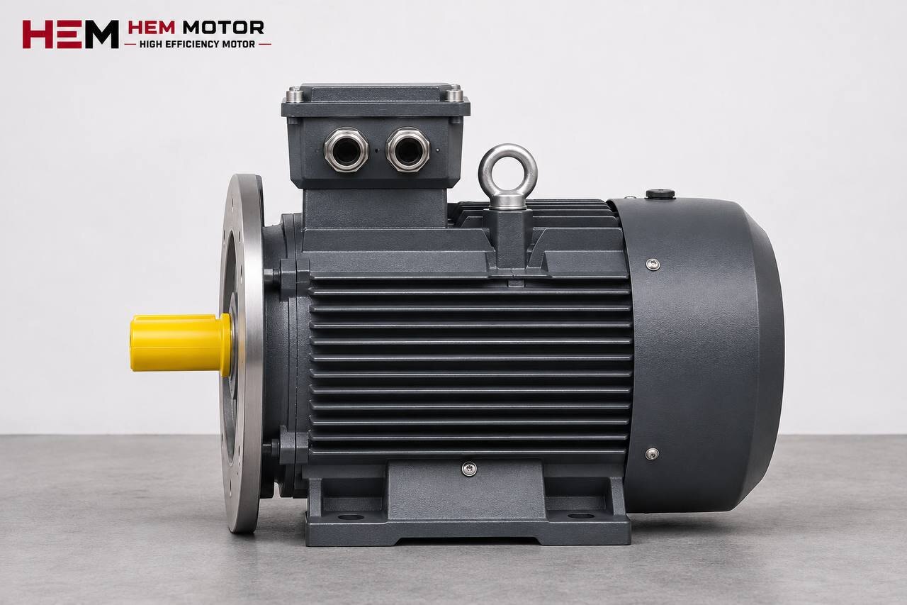
B35 is a foot-mounted frame with a large flange that has through holes. The flange extends beyond the frame diameter, and the bolts pass through its holes and are tightened on the other side. It suits wide mating faces such as pump bearing housings and gearbox input covers.
B34 is a foot-mounted frame with a small face flange. The flange is machined into the face of the end shield and its holes are tapped; the bolt comes from the machine side and screws into the motor flange. It appears in light, compact connections that must fit into a tight space.
For this reason B34 and B35 cannot replace each other. The mating face, the bolt direction and the hole pattern differ; an order placed simply as "foot and flange" can result in a motor that does not fit the driven machine. We cover the flange-only B5 and B14 designs separately on the B5 and B14 flange motors page.
B3, B34 and B35 Side by Side
| Mounting code | Feet and flange | Typical use | What to check |
|---|---|---|---|
| B3 | Feet only; no flange | Coupling or belt drive, machine on a separate base | Shaft height and foot hole spacing |
| B34 | Feet + small face flange with tapped holes | Compact gearbox and mixer groups, tight mounting space | Flange size, spigot diameter, bolt thread; same axis as the feet |
| B35 | Feet + large flange with through holes | Pump, gearbox, crusher and conveyor drive groups | Flange outer diameter and pitch circle, spigot diameter; same axis as the feet |
The table gives a general direction; the final choice is made according to the mating face and the technical drawing of the driven machine.
Two Connections, One Axis: Stress-Free Installation
The most critical point on a foot and flange motor is that both connections are in the right position at the same time. The distance from the foot seating surface to the shaft centre (shaft height) and the axis on which the flange spigot sits must match.
If the base is slightly too high or too low, one of two things happens: either the feet are left floating and the motor still hangs from the flange, or the frame is pulled into place as the bolts are tightened. The second case is more insidious. In a motor mounted under stress, the shaft and bearings run under a constant side load; as general engineering knowledge, this shortens bearing life and increases vibration and heating.
In practice, the following sequence is used:
- First the flange connection is fitted loosely and the spigot is seated in its recess.
- The gap under the feet is measured and, if necessary, filled with thin shim plates. A shim is used to fill a gap, not to push the frame upwards.
- While the foot bolts are tightened, watch whether the flange opens or a gap appears at the face.
- If there is a coupling in between, its alignment is checked again after tightening.
Dimension Check Steps Before Ordering
Giving approximate dimensions for a foot and flange motor means taking two separate mismatch risks at once. If you are replacing an existing motor, we suggest this sequence:
- Note the power, speed, voltage and frame code (IEC) from the motor nameplate.
- Photograph the flange to record whether it has through holes (B35) or is a small face flange with tapped holes (B34).
- Check the foot hole spacing and the shaft height on the existing base.
- Measure the flange outer diameter, pitch circle and spigot diameter; add the shaft diameter and key size.
- Compare these values with the 2D technical drawings and the frame size table.
Flange and shaft dimensions are confirmed separately with every order; completing these steps and sending them to us speeds up matching.
Use on Pump, Gearbox, Conveyor and Crusher Lines
In centrifugal pump groups on a common base, the motor is usually B35: the flange centres on the pump bearing housing and the feet are bolted to the base. For detailed selection, see the pump electric motors page.
On foot-mounted gearboxes, the motor flange enters the gearbox input cover; at high power, foot support stops the gearbox cover from carrying a cantilever load. The topic is covered separately on the electric motors for gearboxes page. On conveyor drives and on crushers running with shock loads, the foot connection is an extra safeguard against vibration loosening the flange bolts.
Example: for an 11 kW 1,500 rpm pump group the 160M-4 can be reviewed, and for a 37 kW gearbox drive the 225S-4. These are examples; the final choice depends on machine load, required speed, mounting and operating conditions.
Price Information and Models in the Shop
The shop price list applies to IE3, 400 V 50 Hz, IP55, insulation class F and the B3 (foot-mounted) design. B34 or B35 versions are not listed as separate products; you choose the model with the same power and speed and state the mounting type in your order. In the catalogue, B3, B5, B14, B34 and B35 as well as the vertical V1/V3/V5/V6/V15 variants are offered depending on the frame. For general mounting options, see the mounting arrangements FAQ.
Medium and high power models are listed in the cast iron frame motors section, and the whole range in the electric motor shop.
Information We Need for a B34/B35 Order
To match the right foot and flange motor quickly, please send: the type of machine the motor will drive, power (kW), speed (rpm), supply voltage, mounting type (B34 or B35, with flange dimensions) and quantity. A photo of the existing motor's nameplate and flange is the fastest route; you can send it via the find an equivalent from the nameplate page or reach us through the contact page. To see the models in advance, browse the shop.
Frequently Asked Questions
How can I tell whether my motor is B34 or B35?
Look at the flange on the front end shield. If the flange extends beyond the frame and bolts pass through its holes, it is B35. If the flange is machined into the face of the end shield, its holes are tapped and the bolt is screwed in from the machine side, it is B34.
Can I bolt a B35 motor to a B3 base by its feet and leave the flange unused?
Mechanically the feet do the same job as on B3; however, in that case centring is provided by coupling alignment, not by the flange. Do not run it before checking the alignment with a dial indicator. For permanent use, ordering a B3 directly is simpler.
Is the price of a foot and flange motor the same as the shop price?
Shop prices are for the B3 design. For B34 or B35, simply choose the model with the same power and speed and state the mounting type; a current quotation is sent based on your order details.
Does putting shims under the feet harm the motor?
Shims used correctly do no harm; they fill the gap between the foot and the base. Damage comes from forcing the frame against the flange axis with shims. If, after tightening, there is a gap at the flange or misalignment at the coupling, the connection should be set up again.
In which power ratings is the foot and flange design available?
Mounting types are offered depending on the frame; the three-phase range covers 0.25–355 kW. For the power and frame you need, flange and shaft dimensions are confirmed with the order.