English
 Français
 Türkçe
 Español
 Русский
 العربية

A flange-mounted motor is a three-phase motor without feet, fixed to the machine through the flange face on its front end shield. It does not rest on a base; its weight is carried by the housing of the equipment it is bolted to. Gearbox inputs, pump lantern housings and drive points built into a machine frame are where this design is most often found. On this page we explain the difference between B5 and B14, the dimensions that define the connection and how to identify the flange on the motor you already have.

When a Footless Motor Is the Right Choice
If the motor shaft has to sit on the same axis as the driven shaft and at a fixed distance from it, a flange connection makes the job easier. As soon as the spigot on the flange enters the recess on the mating part, the axis aligns by itself; there is no lengthy adjustment with shims and dial gauges as with a foot-mounted motor.
Typical examples:
- Direct connection to a gearbox: the motor shaft enters the gearbox input bore and the flange is bolted to the gearbox cover.
- Pump lantern housing: the motor sits on the lantern piece between itself and the pump; the coupling stays inside this housing.
- Drive built into a machine frame: on mixers, fans, feeders or machine-tool units, the machine structure decides where the motor goes.
If the motor is heavy and long, or the housing it is bolted to is not rigid enough to carry that load, a design with both feet and flange is more suitable; we cover this separately on the foot and flange B34 and B35 motors page.
B5 vs B14: Which Side the Bolt Comes From
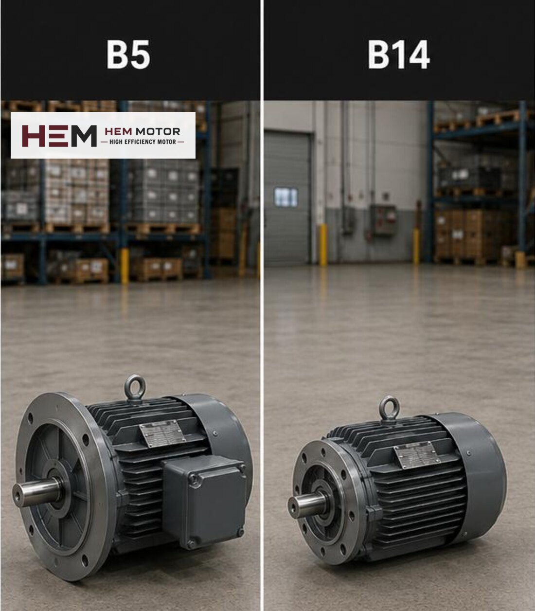
Both types are footless, and from the outside both look like "a round mounting face". The real difference lies in the size of the flange and the type of holes.
A B5 flange is a wide plate that projects beyond the frame diameter. Its holes are clearance holes, meaning they are not threaded. The bolt is passed from the motor side, behind the flange, and tightened into a thread or nut on the mating equipment.
A B14 is a small face flange that stays within the surface of the front end shield. Its holes are threaded; the bolt comes from the front, through the mating equipment, and screws straight into the motor end shield.
This is why B5 and B14 are not interchangeable. The diameter of the mounting face, the pitch circle, the hole type and the bolt direction are all different. Order the same type your machine was machined for; an adapter plate is only a special solution approved by the machine builder.
| Item | B5 (large flange) | B14 (small face flange) |
|---|---|---|
| Mounting face | Wide plate projecting beyond the frame, clearance (unthreaded) holes | Compact face machined on the front end shield, threaded holes |
| Bolt direction | From the motor side, through the back of the flange | From inside the mating equipment, screwed into the motor from the front |
| Commonly paired equipment | Gearbox inputs, pump lantern housings, machine frames | Compact gearboxes, small pumps, units with little space |
| Check when selecting | Flange outer diameter, pitch circle, number of holes, spigot diameter | Face diameter, thread size, pitch circle, spigot diameter |
The table is a conceptual comparison; exact fit is confirmed against the connection dimensions of the mating equipment.
Five Dimensions That Define the Connection
Saying "B5 motor" or "B14 motor" does not complete an order. The same mounting type comes with different dimensions on different IEC frames; these five concepts decide the right fit to the mating equipment:
- Spigot diameter: the diameter of the register on the flange. It is the surface that aligns the axis and must seat fully.
- Pitch circle: the diameter of the circle on which the bolt holes lie.
- Bolt size and number of holes: the hole diameter on B5, the thread size on B14.
- Shaft diameter and shaft length: the part that enters the gearbox bore or the coupling hub.
- Key: key width and keyway; the part that transfers torque to the shaft.
If even one of these values does not match, the motor will not seat, or it will look seated but run with misalignment, wearing bearings and seals early. You can find the actual dimensions by frame in our 2D technical drawings and in the IEC frame size table. The difference between aluminium and cast iron frames is explained on the aluminium frame series page.
Flange Motors for Vertical Operation
A flange motor does not always sit horizontally. On a mixer, a vertical pump or a top-driven unit the motor can be mounted with the shaft facing down or up. Alongside B3, B5, B14, B34 and B35, the catalogue lists the vertical variants V1, V3, V5, V6 and V15 depending on the frame. Because bearing load and exposure to water ingress differ in vertical use, state clearly in the order which direction the motor will run in. For mounting options see also the mounting arrangements question.
Identifying the Flange on Your Existing Motor
When replacing a faulty or ageing flange motor, follow this order instead of guessing:
- Read the nameplate: power, speed, voltage and, where given, the IEC frame code are on the motor nameplate. The frame code is the first piece of information that narrows down flange and shaft dimensions.
- Measure: take the spigot diameter, the pitch circle between holes, the number of holes, whether the holes are threaded or clear, the shaft diameter and the shaft length with a caliper.
- Photograph: shoot the flange straight on, the shaft from the side and the nameplate legibly. Threaded holes mean B14; clear holes on a flange wider than the frame most likely mean B5.
Once these three pieces of information reach us, we can match a motor that fits the same connection from the frame table.
How the Price of a Flange Motor Is Settled
The prices of the 117 models in our shop are given for B3, that is, foot-mounted horizontal design. B5 and B14 versions have no separate product pages. You choose the model with the same power and speed and specify the flange design in the order; once the flange type and the flange and shaft dimensions are confirmed, the price is settled by quotation.
For example, at 1500 rpm the 1.5 kW 90L-4, 4 kW 112M-4 and 7.5 kW 132M-4 are aluminium frame models; the flange design is specified separately on the order and its details are confirmed at the quotation stage. These are examples; the final selection depends on machine load, required speed, mounting and operating conditions. For a general view of pricing, see our electric motor prices page.
What to Send Us for a Quotation
So that we can prepare the right flange motor first time, please send: the type of machine the motor will drive, power (kW), speed (rpm), supply voltage, mounting type (B5, B14 or vertical position), flange and shaft dimensions, and quantity. You can share a photo of the existing motor's nameplate via the nameplate submission page and send flange photos through our contact channels. Standard foot-mounted models and current prices are available in our electric motor shop.
Frequently Asked Questions
Can I fit a B14 flange motor in place of a B5 flange motor?
No. Because the flange size, pitch circle and hole type differ, a B14 motor will not seat on a face machined for B5, nor a B5 motor in a B14 recess. Order the same type as the connection on your machine.
Do two B5 motors with the same kW rating have the same flange?
Not always. The flange and shaft dimensions are set by the IEC frame, not by power; the same power at a different speed can fall into a different frame. Share the frame code from the nameplate and your measured values with us.
Does the shop price also apply to a flange motor?
Shop prices are for the foot-mounted B3 design. When you specify the flange design in the order, the price is given by quotation after the flange and shaft dimensions are confirmed.
Can I use a flange motor vertically?
Vertical variants V1, V3, V5, V6 and V15 are offered depending on the frame. Simply state in the order whether the shaft will face down or up.
Is there an easy way to tell the flange type without measuring?
Look at the holes: if they are threaded it is B14; if they are clear and the flange is clearly wider than the frame, it is B5. Even so, always measure the spigot diameter and shaft dimensions before ordering.