English
 Français
 Türkçe
 Español
 Русский


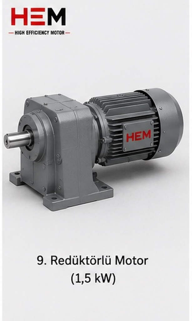
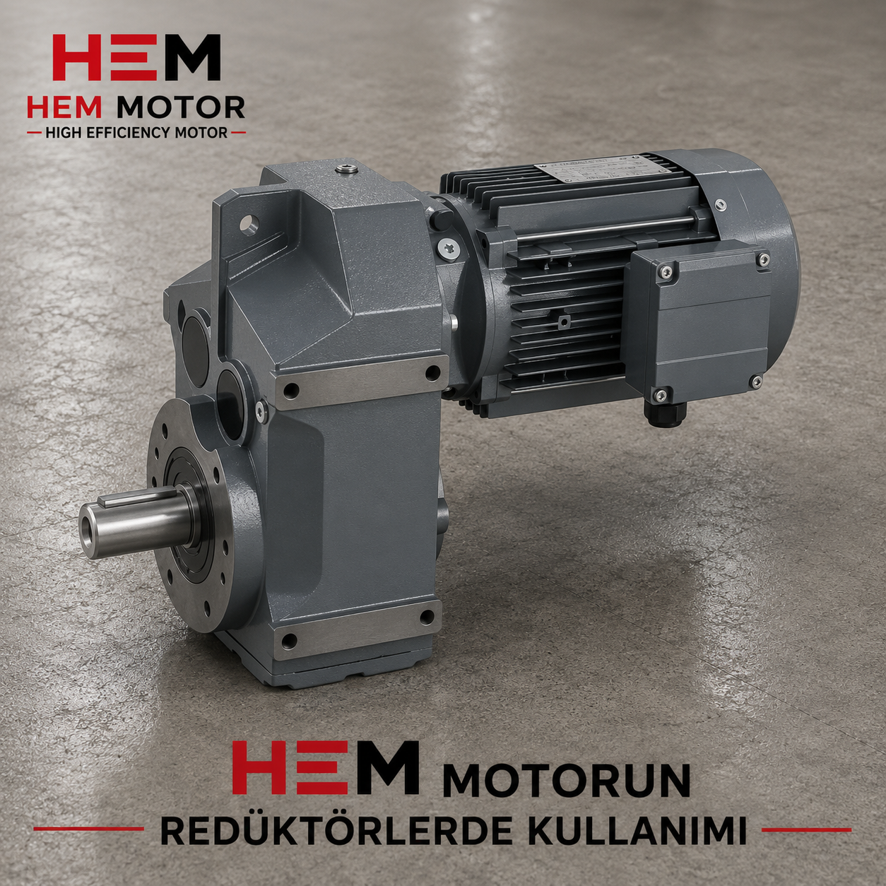
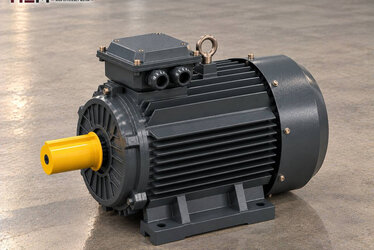
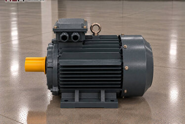
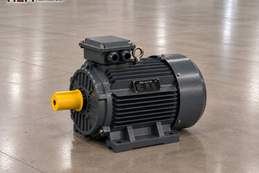
A gear reducer brings the high speed coming from the motor down to the low speed the machine needs and, in doing so, increases the torque on the output shaft by the same ratio. How much torque appears at the reducer output depends on the power and speed of the motor connected to its input. This page explains how standard three-phase asynchronous motors connected to worm, helical, bevel-helical and parallel-shaft reducers are selected; our other application pages are in the electric motors for industries list.

Division of Work Between Motor and Reducer
An asynchronous motor works comfortably at its own speed: a two-pole motor runs at a synchronous speed of about 3000 rpm, a four-pole at 1500 and a six-pole at 1000 rpm. A conveyor drum, a mixer blade or a hoist drum, however, turns at a few tens of revolutions per minute. The reducer bridges the gap. The reducer ratio divides motor speed into output speed; leaving losses aside, output torque is multiplied by approximately the same ratio.
This relationship has two consequences for motor selection. First, motor power comes from the output torque and output speed the machine needs; a motor is not chosen just by looking at the size of the reducer housing. Second, if the motor's number of poles is changed while the reducer ratio stays the same, the machine's speed changes too. A replacement motor must therefore be in the same speed class as the old one.
Reducer Types and Their Effect on the Motor
Worm gear reducer
The worm on the motor shaft turns the bronze wheel on the output shaft; input and output are at right angles. It gives a high ratio in a small volume, is quiet and is common on packaging, small conveyor, door and dosing drives. Because of high sliding friction its efficiency is lower than that of gear reducers; this loss must be added to the motor power. In some high-ratio types back-driving from the output shaft becomes difficult, but this feature must not be used in place of a brake.
Helical and parallel-shaft reducer
Helical gears reduce speed in stages. They are efficient, carry large torques and are preferred on continuously running belt, elevator, mixer and extruder drives. Flat parallel-shaft types can be slipped directly onto a conveyor drum as shaft-mounted units.
Bevel-helical reducer
The bevel gear in the first stage turns the motion through 90°, and the following helical stages complete the ratio. Where both a right-angle layout and high efficiency are wanted, it is used instead of a worm reducer; it is often seen on heavy conveyor and crane travel drives.
The Right Speed for the Reducer Input
Reducer manufacturers' catalogues usually give ratios and output torques for a four-pole input of about 1500 rpm. That is why most geared drives use a four-pole motor. A two-pole motor is smaller and lighter for the same power, but high input speed is not suitable for every reducer in terms of gear and bearing life; check the maximum input speed the reducer allows. A six-pole motor delivers more torque for the same power and can reduce the number of reducer stages on low-speed drives that need a very high ratio.
For example, HEM Motor's 4 kW 112M-4 aluminium model delivers a rated torque of 26.3 Nm at a rated speed of 1,450 rpm. The two-pole 4 kW 112M-2 cast iron model of the same power delivers 13.1 Nm at 2,905 rpm. The input torque to be multiplied by the reducer ratio therefore differs by almost a factor of two depending on the number of poles; detailed values are in our torque table article.
Flange, Shaft and Mounting Fit
On geared drives the first thing to check is the mechanical connection. If the motor sits directly on the reducer's input flange, the motor flange's spigot diameter, fixing holes, shaft diameter and key size must be exactly the same as the reducer input. Small B14 flanges are common on small and medium reducers and large B5 flanges on big reducers. In layouts where a foot-mounted motor and the reducer are joined separately by a coupling, B3 or B34, B35 – which combine feet and flange – are chosen.
HEM Motor offers all of these connections, plus the V1, V3, V5, V6, V15 positions for vertically running drives, according to frame size; flange and shaft dimensions are verified together with you at the order stage. For dimensional checks see the technical drawings and B5 and B14 flange motors pages, and for the foot-and-flange layout the B34 and B35 motors page.
If the motor is connected shaft down or shaft up, bearing load and sealing conditions change; state the position clearly in your order.
Aluminium or Cast Iron Frame?
HEM Motor's aluminium frame series covers 0.25–11 kW and the cast iron frame series 0.55–355 kW. On small and medium motors hung on a reducer by their flange, the lightness of an aluminium frame reduces the load on the reducer flange; packaging, filling and light belt drives fall into this group. On reducers of crusher feeders, heavy belts, mixers and vibrating machines carrying shock loads, the robustness of a cast iron frame comes to the fore. The details of this choice are explained in the aluminium or cast iron question.
Starting, Inverter and Heating
The reducer also multiplies the motor's starting torque by the same ratio. When a full screw conveyor or a loaded belt starts direct-on-line, a sudden shock hits the reducer gears. A frequency inverter or soft starter reduces this shock; an inverter also allows output speed to be adjusted without changing the ratio. If the motor is to run at full torque at low frequency for long periods on an inverter, its shaft-mounted fan slows down and an additional cooling fan may be needed; if the cable between motor and drive is long, a dv/dt or sine filter is considered. Let us know these situations in your order; details are on the inverter-compatible motors page.
On geared drives that stop and start often, a PTC or PT100 sensor for monitoring winding temperature, and an anti-condensation heater for motors standing in humid environments, are order options. On lifting or inclined handling drives that require a brake, state the need for a brake motor in your order.
Example HEM Models for Geared Drives
| Reducer and machine | Motor's task | Value to check when ordering | Example HEM model |
|---|---|---|---|
| Worm, packaging or dosing | Low power, frequent stop-start | B14 flange, shaft diameter | 0.75 kW 80M2-4 aluminium (1,420 rpm) |
| Helical, light belt and elevator | Continuous rotation | Reducer input speed | 2.2 kW 100L1-4 aluminium (1,450 rpm) |
| Bevel-helical, heavy conveyor | Starting under load | Starting method, B5 flange | 7.5 kW 132M-4 cast iron (1,460 rpm) |
| Parallel-shaft, mixer or extruder | High torque, long running | Coupled or flanged | 15 kW 180L-6 cast iron (978 rpm) |
| Large helical, crusher feeder or heavy belt | Shock load | Cast iron frame, foot mounting | 30 kW 200L-4 cast iron (1,475 rpm) |
The table is for guidance only. The right motor is determined by evaluating together the output torque and speed the machine needs, the reducer ratio and efficiency, the connection type and the operating environment.
Geared Applications by Machine
The largest users of geared motors are handling lines; this subject is treated separately on the conveyor belt electric motors and handling systems electric motors pages. Concrete plant mixers, feed mixers and flour mill screw conveyors also run on geared motors.
Information Needed for a Quote
Write the machine the reducer is connected to, the motor power (kW) and speed (rpm), the supply voltage, the mounting type (B14, B5, B3, B34, B35 or a vertical position), the size of the reducer input flange and the shaft diameter, and how many motors you want. Nameplate photos of the old motor and reducer often solve the choice of an equivalent in a single step. Model prices are on the shop pages; our WhatsApp and phone details are on the contact page.
Frequently Asked Questions
Can I fit a 3000 rpm motor instead of a 1500 rpm motor on a geared drive?
If the reducer ratio does not change, the machine turns twice as fast and the output torque is halved. The input speed allowed by the reducer may also be exceeded. Keep the same speed class as the old motor.
The motor flange does not fit the reducer; what should I do?
Send us the spigot diameter, bolt circle and shaft-key dimensions of the reducer input flange. Together we will determine the B5 or B14 flange motor suited to the frame size based on these dimensions.
Why is a more powerful motor chosen for a worm reducer?
The sliding friction between worm and wheel, especially at high ratios, loses more power than gear reducers. This loss must be taken into account using the efficiency given by the reducer manufacturer.
Can I run a geared motor on a frequency inverter?
Yes, our three-phase series are suitable for speed control with an inverter. If there is long running at full load at low speed or a long motor cable, state the cooling and filter requirements in your order.