English
 Français
 Türkçe
 Español
 Русский

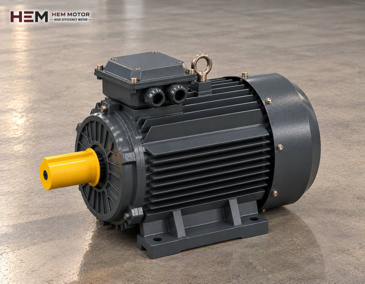
In a helical gear reducer the input shaft and output shaft lie one after the other on the same axis; the motor sits at the back of the reducer and the whole drive looks like one long unit. This layout is common on belt conveyors, mixers, bucket elevators and other continuously rotating machines such as pump-mixer sets. Below, only the three-phase asynchronous motor that turns the reducer input is covered; for a comparison with other reducer types, see the main electric motors for gear reducers page.

The Motor's Role in an Inline Helical Reducer
Inside a helical reducer, pairs of helical gears are arranged in two or three stages. The motor turns the pinion of the first stage; at each stage speed drops a little more and torque grows a little more, and in the last stage the motion reaches the output shaft in line with the motor. Because the teeth mesh with a rolling action, losses are small; most of the power drawn from the motor passes to the output shaft.
The motor's job is to deliver steady, continuous power at the input speed the reducer requires. Output speed is set by the stage ratios; the radial load carried by the drum, mixer blade or chain sprocket on the machine is taken by the reducer output shaft and bearings. The motor does not carry these loads in place of the reducer and does not replace the limits in the reducer catalogue.
Starting Information for Selecting a Motor for a Helical Reducer
The nameplate of this type of reducer usually shows the type code, overall ratio, output speed and sometimes the recommended motor power. The most important motor-related information, however, is the design of the input side: does the reducer come with an IEC input cover that accepts the motor flange directly, or is it driven through a separate input shaft with a coupling? This distinction decides whether the motor will be flange-mounted or foot-mounted.
In addition, the questions are how many hours a day the machine runs, whether the load is steady or fluctuating and whether the machine starts loaded. On machines such as mixers and elevators these three facts show how much margin to leave above the catalogue power value.
Finding Power by Separating Input Speed and Output Speed
Helical reducer catalogues are usually arranged for a given input speed, often the roughly 1500 rpm class of a four-pole motor. So the two speeds should first be written down separately: the motor's rated speed (input) and the output speed the machine needs. The ratio is the one divided by the other. The machine builder gives the output torque and output speed; the output power derived from them, divided by the efficiency stated by the reducer manufacturer, gives the motor power.
| Situation on the machine | Value to check on the motor side | Four-pole sample HEM model |
|---|---|---|
| Light, steady-load belt, continuous rotation | Rated power and speed, adequacy of aluminium frame | 4 kW 112M-4 aluminium (1,450 rpm, 26.3 Nm) |
| Elevator or mixer starting loaded | Starting torque, starting method | 5.5 kW 132S-4 cast iron (1,460 rpm, 36 Nm) |
| Mixer drive with vertical output | V1/V3 mounting, flange load capacity | 11 kW 160M-4 cast iron (1,465 rpm, 71.7 Nm) |
| Long heavy belt, shift operation | Heating in continuous duty, cast iron frame | 18.5 kW 180M-4 cast iron (1,470 rpm, 120.2 Nm) |
The power and speed values in the table are only the motor's own catalogue data; torque and speed at the reducer output depend on your ratio. The examples are not a definitive selection.
If the motor on an existing drive is being replaced, the power and speed on the old motor's nameplate are the first reference. Fitting a more powerful motor may exceed the input power the reducer permits; do not increase power without checking the limit on the reducer nameplate or in its catalogue.
IEC Input Cover, Shaft Bore and Foot Connection
On most inline helical reducers the motor shaft goes into a keyed bore at the reducer input or into a coupling hub, and the motor flange is bolted to the reducer's IEC input cover. The reducer is usually fixed to the machine by its own feet or flange; in that case the motor is chosen without feet, with a flange (B5 or B14). Whatever IEC frame the reducer input cover is machined for, the motor must be of that frame size.
The check sequence can be: IEC frame size, flange type and flange diameter, spigot diameter, number and spacing of bolt holes, shaft diameter and length, key size. If there is a separate input shaft and the motor is connected with a coupling, a foot-mounted (B3) or foot-and-flange (B34/B35) motor is assessed together with foot hole spacing and shaft centre height. Frame dimensions are in the frame size table, dual-mounting types on the B34 and B35 motors page. Until these dimensions match, do not assume that a motor will fit the reducer directly.
In the inline layout the motor extends behind the reducer horizontally or vertically. On mixers with a downward output shaft the motor sits on top in the shaft-down (V1) position; the motor's weight then rests on the reducer input flange. State the position in the order; the arrangements offered for vertical operation are listed in the mounting arrangements question.
Ambient and Cooling Over Long Operating Hours
Thanks to its low losses, a helical reducer stays cooler than the motor; most of the heat in the drive comes from the motor winding. That is why motor cooling comes to the fore on continuously running belts and mixers. If the motor is squeezed into a narrow space behind the reducer or material dust settles on it, air intake through the fan cover is reduced.
Catalogue values apply to ambient temperatures from −15 to +40 degrees Celsius and altitudes up to 1000 m; if the motor will run outside these limits, state this in the order. The motors have IP55 protection and class F insulation and are rated for S1 continuous duty. For dusty or outdoor drives, the answer to the aluminium or cast iron question helps decide which frame to choose.
Limits of Motor and Reducer Under Drives and Load Changes
Inverter speed control is common with helical reducers because belt or mixing speed can be adjusted without changing the ratio. The limit here is usually on the motor side: as frequency drops below 50 Hz the motor's own fan slows, and a separate fan may be needed for long periods at full torque. If the cable run is long, a dv/dt or sine filter is considered. Details are on the inverter-compatible motors page.
Going above 50 Hz creates a limit on the reducer side: input speed rises and the reducer's maximum permitted input speed may be exceeded. The shock that direct-on-line starting puts on the gears of an elevator starting loaded or a mixer stopped with a dense mix can be reduced with an inverter or soft starter. For frequent stop-start or heavy load, a PTC or PT100 sensor monitoring winding temperature is an order option.
Information to Send With a Replacement Request
To choose a new motor in place of a failed one, photos of the motor and reducer nameplates are often enough. You can send them via WhatsApp following the steps on the find an equivalent from the nameplate page.
- Motor nameplate: power, speed, voltage, current and connection
- Reducer nameplate: type code, ratio, output speed
- Connection type: flange to the IEC input cover, or foot-mounted with coupling
- Flange type and diameter, shaft diameter and length
- Drive orientation: horizontal or vertical with output down
- Daily operating time of the machine and inverter use
- How many motors are required
Our phone and WhatsApp details are on the contact page.
Product Groups in the Shop to Look at for Helical Drives
For helical drives on light belt and packaging lines, aluminium frame motors, and for heavy belts, elevators and mixers, cast iron frame motors are the first groups to look at. To narrow the list by speed class, look at the four-pole (1500 rpm class) models; all models are in the electric motor shop.
The 5.5 kW 132S-4 and 11 kW 160M-4 cast iron models in the table above are examples; their suitability for your machine and reducer is confirmed separately with flange, shaft and load data. Our site also has a foot-mounted helical gear reducers category; this page covers only motor selection, and the reducer is chosen separately from its own data.
Frequently Asked Questions
Why is the motor hotter than the reducer on a helical drive?
Because the gears mesh with a rolling action, reducer losses are small and most of the heat in the drive is produced in the motor winding. A motor housing hotter than the reducer does not on its own indicate a fault; compare the current with the nameplate value.
Can I run the motor above the 50 Hz mains frequency to increase belt speed?
Frequency can be raised with an inverter, but the reducer input speed rises in the same proportion. Do not do this without checking the maximum input speed in the reducer catalogue and the motor torque at that speed; changing the ratio is often the better solution.
My reducer is foot-mounted; should the motor have feet too?
If the motor connects to the reducer's IEC input cover with a flange, a flange motor without feet is usually chosen. A foot-mounted motor is needed only if the reducer is driven through a separate input shaft with a coupling or if additional foot support is wanted.
Does fitting a more powerful motor protect the reducer?
No, it can do the opposite. An oversized motor transmits higher torque to the reducer when the machine jams. Motor power is chosen by considering the reducer's permitted input power and the machine's real load together.