English
 Français
 Türkçe
 Español
 Русский

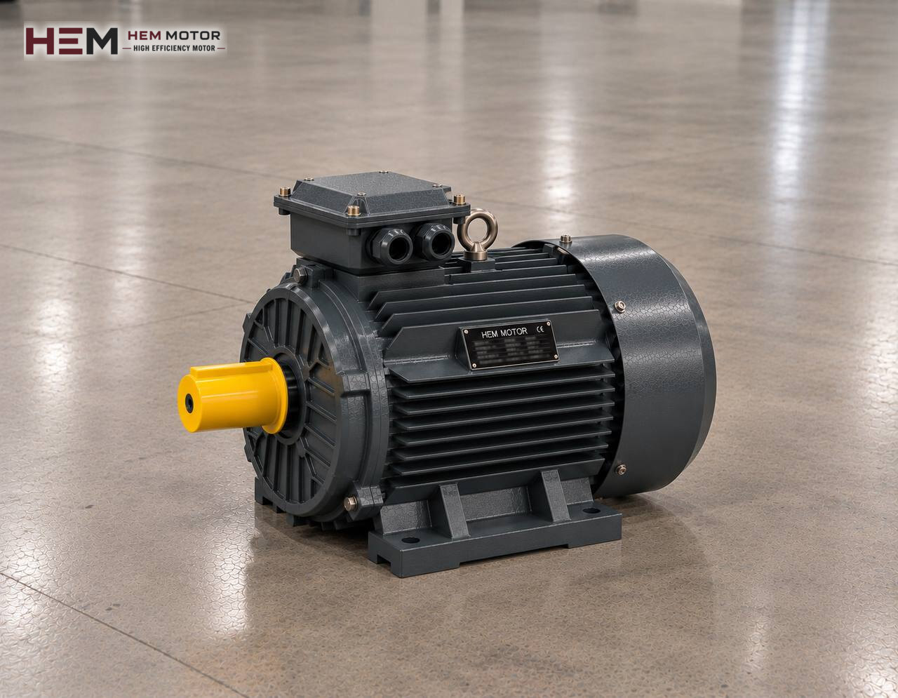
In a parallel-shaft gear reducer the input and output shafts are parallel to each other but not on the same axis; the flat housing rests against the side of the machine, and the hollow output shaft is often slid directly onto the machine shaft. Belt drums, bucket elevators, mixers and long screw conveyors are typical users of this shaft-mounted layout. What is described here is the three-phase asynchronous motor that drives this flat reducer; other reducer types are covered under electric motors for gear reducers.

What the Motor Does and Does Not Do in a Shaft-Mounted Drive
The motor turns the reducer's input pinion; the motion passes through two or three helical stages to reach a hollow or solid output shaft. In hollow-shaft types the reducer is slid onto the machine shaft with a keyed or shrink-disc connection and tied to the machine frame by a torque arm to stop it rotating. In this case motor and reducer hang on the machine shaft as a single package.
The torque arm that stops the drive rotating, the support of the reducer on the shaft and the bending of the machine shaft are not motor matters; they are solved by the reducer and machine design. The motor's job is to deliver power to the input shaft at the required speed. Even so, the motor's weight and length directly affect the balance of the hanging package, so they are dealt with separately in selection.
Information Required When Choosing a Motor for a Parallel-Shaft Reducer
From the reducer you need type and size, overall ratio, whether the output shaft is hollow or solid, the IEC connection size on the input side and the mounting position. From the machine you need the required output speed and torque, daily operating time, whether the load is smooth or shock-type and whether it starts loaded or empty.
There is one more question specific to shaft mounting: on which side of the reducer and at what angle is the motor attached? On parallel-shaft reducers the motor can sit above, below or beside the output shaft; this position determines both the direction of the torque arm and how close the motor is to the floor.
Assessing Motor Speed, Output Speed and Power Separately
Only two values are selected on the motor side: power (kW) and the rated speed set by the pole number. Output speed results from dividing this input speed by the reducer's overall ratio; output torque is the motor torque multiplied by the ratio and the reducer efficiency. Parallel-shaft helical reducers are gear reducers whose stages work with a rolling action; even so, the efficiency used in the calculation is taken from the reducer manufacturer's table.
| Shaft-mounted application | Nature of the load | Attention in motor selection | Sample HEM model |
|---|---|---|---|
| Belt conveyor drum | Continuous, loaded start | Starting method, four poles | 15 kW 160L-4 cast iron (1,465 rpm) |
| Bucket elevator head shaft | Vertical load, tendency to run back | Backstop arrangement on the machine, whether a brake motor is needed | 11 kW 160M-4 aluminium (1,465 rpm) |
| Horizontal mixer shaft | High torque, fluctuating load | Cast iron frame, PTC sensor | 18.5 kW 200L1-6 cast iron (980 rpm) |
| Long screw conveyor | Risk of jamming, long running | Current monitoring, heating in continuous duty | 45 kW 225M-4 cast iron (1,485 rpm) |
The models in the table are examples and not a definitive selection; the actual power is calculated from the machine's output torque, the reducer ratio and its efficiency.
If the motor on a running machine is being replaced, the power and speed on the old motor's nameplate are the first reference. If the machine speed is to be changed, the reducer ratio or the inverter setting is usually changed; fitting a motor with a different pole number changes both output torque and the reducer's input condition.
Flange, Shaft and Motor Weight on a Hanging Package
On parallel-shaft reducers the motor is usually connected to the IEC input adapter with a B5 flange; the motor shaft goes into the coupling hub or keyed bore inside the adapter. Because the package hangs on the machine shaft, the motor is chosen with a flange rather than feet, and its entire weight rests on this flange connection. For this reason flange type and diameter, spigot diameter, bolt hole spacing, the shaft's diameter and length and the key width must be compared one by one with the reducer input.
The IEC frame size is the starting point for this comparison; the motor's body length and centre of gravity also affect the balance of the hanging package. For the same power an aluminium frame is lighter and a cast iron frame sturdier; which one suits a shaft-mounted drive is assessed against the motor load the reducer manufacturer permits. The technical drawings and the frame size table can be used for the dimension comparison. Do not assume a new motor can be fitted to the hanging package until the dimensions match one by one.
On types with a separate input shaft, the motor can be foot-mounted (B3) or foot-and-flange (B35) and connected by coupling or belt; in this layout the hole distance between the feet and the height of the shaft axis above the base are also measured. Mounting options are in the mounting arrangements question.
Ambient Conditions for a Motor Working Beside the Machine
In the shaft-mounted layout the motor sits right beside the machine, often next to the belt drum or the screw housing. Material spilled under the drum, dust at the screw outlet and water splashed during cleaning can reach the motor directly. Since the motor draws its cooling air through the fan cover, care must be taken that the front of the cover is not blocked by material build-up.
The rating data in the catalogue are given for installations with ambient air from a minimum of minus 15 to a maximum of plus 40 degrees Celsius and up to 1000 metres above sea level; a colder, hotter or higher site must be stated in the order. IP55 protection is designed against dust and splashing water; it is not designed for pressure washing. For motors that stand idle for long periods and absorb moisture, a condensation heater is an order option.
Drives, Long Running and Shock Loads
Parallel-shaft drives usually run without interruption throughout a shift. If speed is controlled by an inverter, the motor's own fan slows at low frequency; if it stays at low speed with full torque for a long time, a separate fan may be needed. If the cable distance between drive and motor is large, fitting a dv/dt or sine filter at the output is considered. Note inverter operation in the order; our page on the subject: inverter-compatible motors.
When material jams in a mixer or screw, motor current rises quickly and a large torque reaches the reducer. A current-monitoring protection device and a PTC or PT100 sensor fitted in the winding protect the motor in this case; to protect the drive mechanically, solutions such as a torque-limiting coupling are considered on the machine side. On bucket elevators the backstop arrangement is on the machine side; specify in the order if a brake motor is needed.
Information to Send With a Replacement Order
For a motor removed from a shaft-mounted drive, you can send a photo of the motor and reducer nameplates via WhatsApp as described on the find an equivalent from the nameplate page. If the nameplate cannot be read, the following information helps:
- Motor power, speed, voltage and connection type
- Reducer type, size and ratio; whether the output shaft is hollow or solid
- Flange type and diameter of the input adapter
- Diameter, length and key of the motor shaft
- Position of the motor relative to the reducer and direction of the torque arm
- Machine type, operating time and inverter use
- How many motors are needed
To reach us, you can use the WhatsApp line on the contact page.
Shop Groups to Look at for Hanging-Package Drives
For heavy belts, screw conveyors and mixers, cast iron frame motors, and for medium-power hanging packages where motor weight matters, aluminium frame motors are the product groups to look at. You can see the full range on sale on our shop page.
The 15 kW 160L-4 and 18.5 kW 200L1-6 cast iron models in the table are examples; whether they suit your machine is confirmed separately by comparing dimension, weight and load data. Parallel-shaft housings are listed on our site under helical parallel-shaft gear reducers; the content here is limited to the motor.
Frequently Asked Questions
Should the motor on a hollow-shaft reducer have feet?
Usually not. Because the reducer hangs on the machine shaft, the motor moves together with the package and is connected to the reducer's input adapter by a flange. A foot-mounted motor is used only in a layout with a separate input shaft and coupling.
Does a heavier motor cause problems on a shaft-mounted reducer?
Motor weight puts extra load on the input flange and the torque arm. The motor weight and frame length permitted by the reducer manufacturer should be checked; if necessary, a lighter frame of the same power should be considered.
How do I protect the motor when the screw conveyor jams?
A correctly set motor protection relay and a PTC sensor in the winding protect the motor against overheating. Mechanical solutions such as a torque limiter are considered on the machine side to protect the reducer and the machine.
Should I change the motor to change belt speed?
Usually not. For a small speed difference an inverter, for a large one a change of reducer ratio is the better route. A motor with a different pole number also changes output torque and can upset the reducer's input condition.