English
 Français
 Türkçe
 Español
 Русский

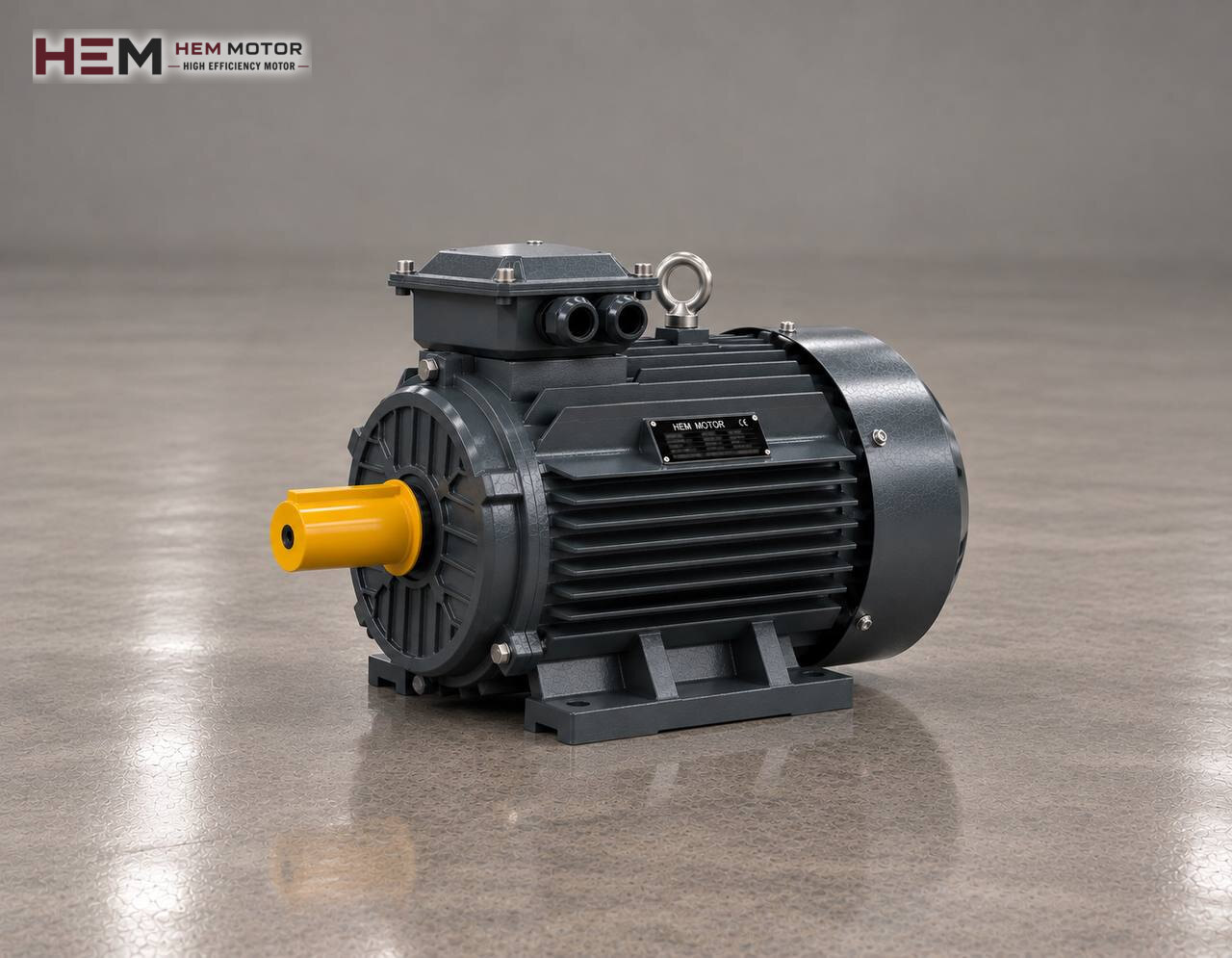
Because a worm gear reducer can bring the high speed of a motor down to a very low output speed in a single stage, it is common on packaging lines, dosing screws, small conveyors and gate or barrier drives. This page deals only with the three-phase asynchronous motor connected to the input of such a reducer; a general comparison of reducer types is on the electric motors for gear reducers page.

What Does the Motor Turn in a Worm Gear Reducer?
Inside the reducer housing there is a steel worm turned by the motor shaft and a mating wheel, usually made of bronze (the worm wheel). The motor turns only the worm. Each turn of the worm advances the wheel by only one or a few teeth, so the output shaft rotates far below motor speed and on an axis at right angles to the motor shaft.
Separating the jobs the motor does not do makes selection easier. Output speed is set by the reducer ratio, not by the motor. Holding a stationary load is not the motor's task either: some high-ratio worm reducers are hard to back-drive from the output, but this behaviour changes with vibration, temperature and wear and does not count as a brake. Shocks and axial loads on the output shaft are carried by the reducer's wheel, bearings and housing.
Which Data Should Be Collected to Choose a Motor for This Reducer?
Motor selection starts from the reducer nameplate. The nameplate or reducer catalogue shows the type, the ratio (i), the permitted input power and input speed, the IEC size of the input flange and the bore diameter at the worm input. To these are added the output speed and output torque the machine needs, the daily operating time and the number of starts per hour.
| Data to collect | Where it comes from | What it does in motor selection |
|---|---|---|
| Reducer ratio and permitted input speed | Reducer nameplate or catalogue | Sets the motor pole number (speed class) |
| Required output torque and speed | Machine builder or existing design | Gives motor power together with reducer efficiency |
| Input flange and hollow shaft bore | Reducer dimension drawing, on-site measurement | Shows IEC frame size and B14/B5 flange type |
| Mounting position of the reducer | Layout on the machine | Decides whether the motor is horizontal, shaft down or shaft up |
| Number of starts and direction reversals | Machine operating schedule | Shows winding heating, sensor and drive needs |
The headings in the table are a data list; none of them alone amounts to a definitive motor selection.
Allowing for Reducer Efficiency When Setting Power and Speed
Output speed is roughly the motor's rated speed divided by the reducer ratio. The required motor power is the product of output torque and output speed divided by 9550 and by the reducer efficiency. In the worm type this last term is decisive: because there is sliding friction between worm and wheel, efficiency is lower than in gear reducers, and it falls further as the ratio rises and at the moment of starting. Take the efficiency value not from a guess but from the table the reducer manufacturer gives for that ratio and input speed.
If you have a working machine, the most reliable starting point is the nameplate of the existing motor. The power and speed on it have been proven against the load the reducer has seen for years. If the machine should run faster or slower, the usual way is to change the reducer ratio; changing the motor's pole number upsets both output torque and the reducer's input condition.
Motor-side figures can be read from the catalogue. For example, the 0.55 kW 80M1-4 aluminium model gives 3.75 Nm rated torque at 1,400 rpm, and the 1.1 kW 90S-4 aluminium model gives 7.27 Nm at 1,445 rpm. These are values at the motor shaft; torque at the reducer output is this value multiplied by the ratio and the reducer efficiency. The torque difference by pole number is shown in our torque table article.
Four-pole motors of about 1500 rpm class are common on worm reducers. A two-pole motor increases the sliding speed on the worm; the reducer's permitted input speed may be exceeded and heating increases. A six-pole motor gives a lower output speed with the same ratio; this route should be considered only if the reducer data also covers that input speed.
Connecting to the Worm Input: Flange, Hollow Shaft and Key
On most worm reducers the motor shaft, with its key, goes into the hollow input of the worm and the motor flange is bolted to the reducer input flange. There is no coupling; the motor hangs on the reducer. The first item to check is therefore the motor's IEC frame size (63, 71, 80, 90…), because shaft diameter and flange dimensions depend on the frame. The frame size table can be used for dimension equivalents.
Small reducers use the small B14 flange with threaded holes, larger ones the large B5 flange with through holes. Since more than one B14 flange size may exist for the same frame, the outer diameter, spigot diameter and hole spacing of the flange must be measured. Other values to compare are shaft diameter and length, key width, number of holes and how close the terminal box comes to the reducer housing. If motor and reducer are connected separately with a coupling, the foot hole spacing and shaft height of the foot-mounted motor also go on the list. Without these checks it cannot be said that a motor will mount straight onto the reducer. Flange options are on the B5 and B14 flange motors page.
Because a worm reducer can be installed with the worm on top, underneath or at the side, the motor is not always horizontal. If the motor sits shaft down (V1) or shaft up (V3) on the machine, state this in the order; these positions change bearing load and where water collects on the motor. Available mounting arrangements are listed in the mounting arrangements question.
Ambient Conditions Next to a Hot Reducer Housing
In a worm reducer the power lost through sliding friction turns into heat, so the housing runs hotter than gear reducers at the same load. The motor flange is bolted to this hot housing, and the motor's own fan cools only the motor, not the reducer. In an enclosed compartment such as a packaging machine cabinet, warm air recirculates; leave a space behind the motor fan cover from which it can draw air.
HEM Motor catalogue values apply to ambient temperatures from −15 to +40 degrees Celsius and altitudes up to 1000 m. If the motor compartment exceeds this limit or the site is higher, state this in the order. The series comes with IP55 protection and class F insulation. A condensation heater for washed or night-cooled environments and a PTC or PT100 sensor to monitor winding temperature are order options.
Stop-Start Duty, Inverters and Low-Speed Running
In applications such as a dosing screw, a gate or a packaging station, the motor starts many times per hour. The high current drawn at each start heats the winding; a PTC sensor fitted in the winding makes protection easier in this kind of duty. A worm reducer has higher internal friction when moving off from standstill, so the motor's starting torque must cover that moment; the starting efficiency in the reducer catalogue is used for this check.
When speed is reduced with a frequency inverter, two effects appear together: the motor's shaft-mounted fan slows down, and reducer efficiency changes because the sliding speed of the worm also falls. A motor that will run at full torque at low frequency for long periods may need a separate fan; if the motor cable is long, a dv/dt or sine filter is considered. Report these conditions in the order; details are on the inverter-compatible motors page. In reversing gate and barrier drives, specify in the order if a brake motor is needed; load-holding safety is a matter of machine design.
Which Information Should You Send When Replacing the Old Motor?
For a motor removed from a reducer, the quickest way is to send photos of the motor and reducer nameplates via WhatsApp following the steps on the find an equivalent from the nameplate page. If the nameplate cannot be read, the measurements below give enough information.
- Photo of the motor nameplate: power (kW), speed (rpm), voltage and connection (Δ/Y)
- Reducer nameplate: type, ratio and permitted input speed
- Flange type (B14 or B5), flange outer diameter and hole spacing
- Motor shaft diameter, shaft length and key width
- Position of the reducer on the machine and motor orientation (horizontal, V1, V3)
- Approximate starts per hour and whether an inverter is used
- Required quantity
With this information, machine type and operating time are assessed together; our WhatsApp and phone details are on the contact page.
Motors in the Shop Worth Reviewing for Worm Drives
Since worm reducers are mostly used at small and medium power, lightweight aluminium frame motors hanging on the flange are the first group to look at; for drives with shock loads or in harsh environments, cast iron frame motors can also be reviewed. All models are listed in the electric motor shop.
Four-pole examples: 0.37 kW 71M2-4 aluminium (1,340 rpm), 0.55 kW 80M1-4 aluminium (1,400 rpm), 1.1 kW 90S-4 aluminium (1,445 rpm) and 3 kW 100L2-4 aluminium (1,450 rpm). These models are given only as examples; their suitability for your reducer and machine is confirmed separately with flange, shaft and load data. For the reducer housing, see the worm gear reducer category on our site; the suggestions on this page cover the motor only, and the reducer is selected separately from its own data.
Frequently Asked Questions
The worm reducer housing is very hot; is the problem in the motor?
In this type of reducer the lost power turns into heat, so it is normal for the housing to run hotter than gear reducers. Compare the motor current with the nameplate value; if the current is normal, oil level, ratio and load should be checked on the reducer side.
Can I fit a two-pole motor instead of a four-pole one?
If the ratio stays the same, output speed roughly doubles and output torque drops; the sliding speed on the worm also rises. Stay in the same speed class as the old motor so as not to exceed the reducer's permitted input speed.
Does the reducer's self-locking replace a brake?
No. Although some high-ratio worm reducers resist back-driving, this behaviour weakens with vibration and wear. On machines that must hold a load, the brake and safety arrangement are solved separately in the machine design; specify in the order if a brake motor is needed.
What should I measure when ordering a B14 flange motor?
Measure the flange outer diameter, spigot diameter, bolt hole spacing and thread size, as well as shaft diameter and shaft length. Since different B14 sizes may exist on the same frame, the frame number alone is not enough.
Can a single-phase motor be used on a small worm drive?
If there is no three-phase supply, our single-phase motor series in the 0.18–5.5 kW range can be considered. The starting torque and flange dimensions of the single-phase motor must be checked against the starting needs of the reducer.