English
 Français
 Türkçe
 Español
 Русский

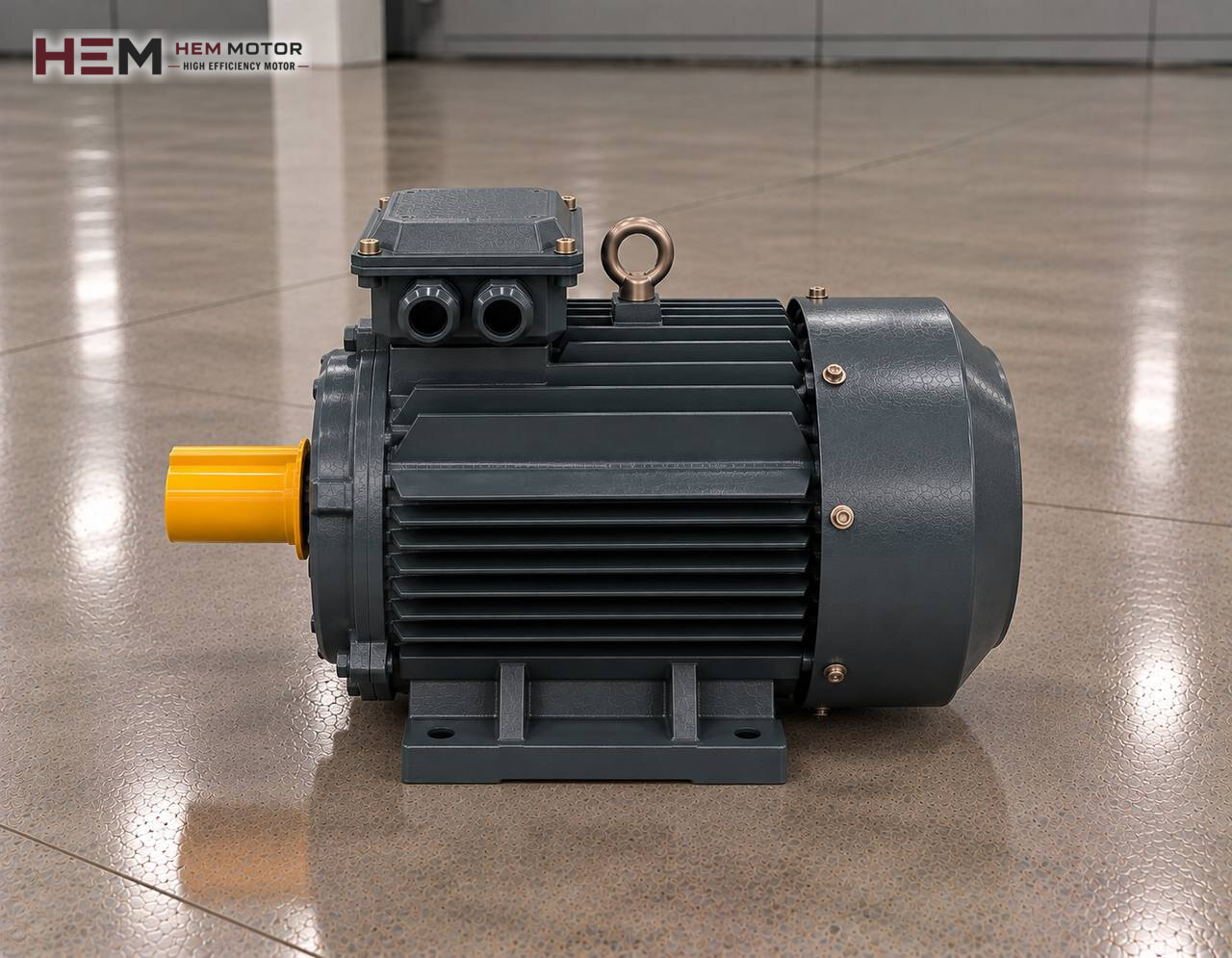
A bevel-helical gear reducer turns the motion through 90 degrees with the bevel gear pair in its first stage; while the motor lies parallel to the machine, the output shaft connects at a right angle to the machine's drum, travel wheel or mixer shaft. This layout is sought on heavy belts with limited space, crane travel drives, screw conveyors and large mixers. This page explains how to select the three-phase asynchronous motor that turns the input of such a reducer; the parent topic is on the electric motors for gear reducers page.

The Stage the Motor Turns in a Right-Angle Drive
The motor turns the small bevel pinion on the input side of the reducer. The pinion turns the bevel wheel opposite it, and the motion turns 90 degrees and passes to the helical stages; the last stage turns a solid or hollow output shaft. Because the motor speed reaches the bevel gear at its highest in the first stage, the gears and bearings of this stage are the most sensitive point and set the input speed the reducer allows.
The motor does not change the direction; the right angle is created by the reducer's bevel stage. The machine load on the output shaft, the radial force coming through a drum or wheel and the braking torque in travel drives are matters for the reducer and the machine's supporting structure. The motor only gives rotation to the input shaft at the required speed and power.
What to Read From the Bevel-Helical Reducer Nameplate
On this type of reducer the nameplate or catalogue line usually contains type and size, overall ratio, output speed, mounting position and the IEC size of the input connection. Whether the output shaft is hollow or solid, whether a torque arm is used on the machine side and which face of the reducer points down should also be recorded; this last item directly affects the motor's orientation.
The output speed and torque required by the machine, the drive's daily operating time, the number of starts per hour and the size of the load inertia (for example a travelling crane bridge or a long belt) are the other data needed for motor selection.
Finding Input Speed, Output Speed and Motor Power
The calculation uses two separate speeds: the motor's rated speed is the reducer's input speed, and the speed the machine needs is the output speed. Output speed is found by dividing input speed by the overall ratio. Motor power is obtained by dividing the power derived from output torque and output speed by the reducer efficiency. Bevel-helical reducers belong to the gear reducer group and run with lower losses than sliding-friction types; even so, the efficiency used in the calculation is the value the reducer manufacturer gives for that size and ratio.
| Right-angle application | Key point in the calculation | Decision on the motor side | Sample HEM model |
|---|---|---|---|
| Crane or trolley travel | Inertia, frequent start-stop | Inverter, need for a brake motor | 4 kW 112M-4 cast iron (1,450 rpm) |
| Inclined heavy belt conveyor | Starting with a loaded belt | Starting method, cast iron frame | 7.5 kW 132M-4 cast iron (1,460 rpm) |
| Large-diameter mixer | Low output speed, high torque | Six-pole option, reducer input limit | 11 kW 160L-6 cast iron (970 rpm) |
| Long screw conveyor drive | Material jamming, long running | PTC sensor, heating in continuous duty | 22 kW 180L-4 cast iron (1,470 rpm) |
These rows show points to consider by application; motor power and model are not a definitive selection and are calculated separately from reducer data and machine load.
If the motor on an existing drive is replaced, the power and speed on the old motor's nameplate are the basis. A six-pole motor gives a lower input speed and, with the same ratio, a lower output speed; this choice only makes sense if the output speed the machine needs is changing and the reducer is catalogued for that input speed.
Flange, Shaft and Position Checks at the Bevel-Helical Input
On bevel-helical reducers the motor is usually connected to the reducer's IEC input adapter with a B5 flange; the motor shaft goes into the coupling half or keyed bore inside the adapter. Some types have a separate input shaft, and the motor is then foot-mounted and connected by coupling or belt and pulley. Which one is used can be seen by looking at the input side of the reducer.
The dimensions to compare start with the IEC frame number, followed by flange outer diameter, spigot diameter, bolt hole spacing, shaft diameter, shaft length and key. For belt drives, foot hole spacing and shaft height are added. Until the dimensions have been compared with the technical drawings and the frame size table, it cannot be said that a motor will fit this reducer directly.
Because of the right-angle design, the motor can stay horizontal whatever the direction of the output shaft; however, when the reducer is mounted on its side or upside down, the motor can move into a vertical position. Whether the motor will stand shaft down (V1) or shaft up (V3), which way the terminal box will face and the position of the cable entry should be specified in the order. Available options are in the mounting arrangements question; flange types are on the B5 and B14 flange motors page.
The Motor in Outdoor, Dusty and High-Altitude Conditions
Bevel-helical drives often run on belts in open yards, on port and warehouse cranes or on dusty mixer platforms. The right-angle layout places the motor beside the machine, sometimes just above the travel path; there the motor is directly exposed to rain, snow, sun and splashing material. The motors have IP55 protection and class F insulation; even so, there should be no pocket on top of the motor where water can collect, and in the shaft-up position a protective canopy should be considered if needed.
Catalogue values apply from −15 to +40 degrees Celsius and up to 1000 m altitude; if the site is colder in winter, hotter in summer or higher, this should be stated in the order. For motors that absorb moisture during long standstills, a condensation heater is an order option.
Using an Inverter for Travel Drives and Heavy Starts
In applications such as crane trolley or bridge travel, the motor accelerates and decelerates a large mass every time. With direct-on-line starting, this inertia reaches the bevel stage as a sudden torque shock. An inverter softens acceleration with ramp times and reduces load sway. If the motor will run at full torque at low frequency for long periods, its own fan may be insufficient and a separate fan may be needed; if the motor cable is long, a dv/dt or sine filter is considered. Details are on the inverter-compatible motors page.
In travel and inclined conveying drives, specify in the order if a brake motor is needed; safety arrangements such as load holding, storm locks and limit switches are the responsibility of the machine builder and are assessed separately from motor selection. A PTC or PT100 sensor can be added to monitor winding temperature with frequent starts. For crane drives, see also the lifting and handling crane motor page.
Information to Send When Replacing the Motor
For a motor removed from a bevel-helical reducer, clear photos of the motor and reducer nameplates plus a few measurements are usually enough. You can send them via WhatsApp as described on the send the motor nameplate page.
- Motor nameplate: power, speed, voltage, frequency and connection
- Reducer nameplate: type, size, ratio and mounting position
- Input connection: flange to the IEC adapter, or coupling from a separate input shaft
- Flange diameter, shaft diameter and length, key size
- Motor orientation and direction of the terminal box
- Ambient information such as open yard, dust or high altitude
- Need for a brake motor and required quantity
Our contact details are on the contact page; requests are handled by WhatsApp and phone.
Motor Groups in the Shop for Right-Angle Drives
Since bevel-helical reducers are common at medium and high power, cast iron frame motors are the priority group in most applications; at lower powers aluminium frame motors can also be considered. Six-pole (1000 rpm class) options are in the same list; the whole series is in the electric motor shop.
The 7.5 kW 132M-4 and 11 kW 160L-6 cast iron motors in the table are given as examples; their suitability for your drive is confirmed separately with dimension and load data. For the reducer housing, our site has a bevel-helical gear reducers category; the suggestions on this page cover the motor only.
Frequently Asked Questions
I replaced a worm reducer with a bevel-helical one; do I need to change the motor too?
Because a bevel-helical reducer runs with lower losses, a smaller motor may be enough for the same output torque, but the decision is made by calculation with the new reducer's efficiency and ratio data. The input flange and shaft dimensions must also be checked against the new reducer.
Can a two-pole motor be connected to a bevel-helical reducer?
Because the bevel gear in the first stage runs at the highest speed, the reducer's permitted input speed is decisive. If the catalogue does not allow this speed, a two-pole motor should not be used; in most applications a four-pole motor is preferred.
Does the motor position change when the reducer is mounted upside down?
Yes. When the reducer mounting position changes, the motor may move from horizontal to vertical and the terminal box may face another direction. In that case the motor's V1 or V3 position and the cable entry must be specified separately in the order.
Is a standard motor sufficient for crane travel?
The motor only provides the travel motion; braking, stopping and the safety arrangement belong to the machine design. Specify in the order if a brake motor is needed, and also send the frequent-start and inertia information.