English
 Français
 Türkçe
 Español
 Русский

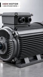
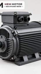
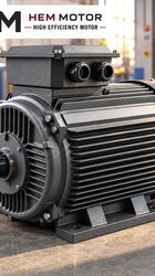
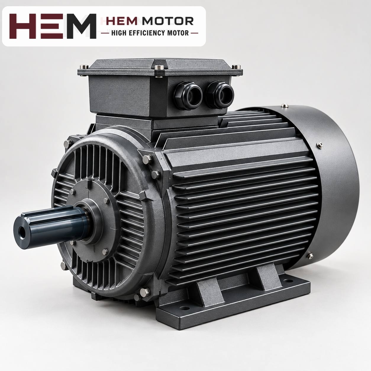

A cooling tower is a heat exchanger that cools process water or air-conditioning condenser water by bringing it into contact with air. The fan on top of or beside the tower continuously discharges warm, humid air. This is why the electric motor that turns the tower fan works in one of the most humid operating environments in industry: splashing water droplets, condensation, open air, sun and frost can all occur over the life of the same motor. In this article we explain clearly what to watch out for regarding humidity and mounting when choosing and replacing a cooling tower fan motor, and what a standard motor does and does not cover.
Tower fan drive arrangements: where does the motor stand?
On cooling towers the connection between fan and motor is made in several different ways. The amount of moisture the motor will face depends largely on this arrangement.
- Gearbox drive (with drive shaft): On large towers the fan is connected to a slow-running right-angle gearbox. The motor usually stands outside the fan stack and transmits power to the gearbox through a long drive shaft. The purpose of this arrangement is to keep the motor away from the humid air flow.
- Belt and pulley drive: On medium-sized towers the motor is connected to the fan shaft by belt. The motor is placed on a platform beside the tower casing or close to the air inlet area; depending on its position, it may be directly exposed to splashing water.
- Direct-coupled drive: On small and packaged towers the fan propeller is fitted directly onto the motor shaft. The motor usually runs in a vertical position, just below or above the fan and inside the humid air flow.
If the motor is inside the air flow, it is continuously cooled by humid air and the risk of condensation is at its highest. If it is outside the flow, it faces only outdoor conditions. Before replacement, note which of these three arrangements the motor is in.
What does IP55 cover, and what does it not?
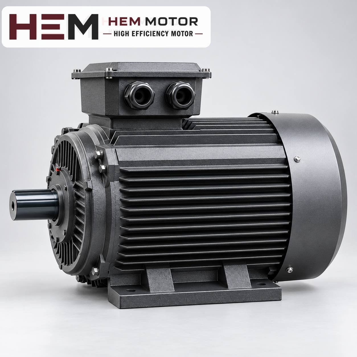
All of our models on sale are IP55-rated. Knowing exactly what this rating means prevents false expectations on a cooling tower.
- First digit (5): Protected against dust. Ingress of dust is not completely prevented, but it does not enter in amounts that would impair the motor's operation.
- Second digit (5): Protected against low-pressure water jets from any direction. Rain, splashing droplets and briefly hosing with water fall within this scope.
The situations IP55 does not cover are also clear:
- The motor running continuously inside the water curtain, the water escaping from the drift eliminators or dense water vapour.
- Condensation water accumulating inside the frame. The IP rating defines protection against water from outside; it does not prevent the air inside the motor from cooling and condensing.
- Immersion of the motor in water or high-pressure washing.
- The effect of chemically treated water vapour, salty environments or aggressive atmospheres on paint and metal surfaces.
For this reason, IP55 is an adequate starting point for many positions on a tower; but if the motor is directly inside the humid air flow or exposed to constant splashing, it may not be enough on its own. Additional needs such as a condensation drain hole, anti-condensation heater, extra surface protection or a higher protection rating are stated in the order and their suitability is assessed together. These should not be assumed to be part of the standard model.
Condensation: the silent risk for tower motors
Tower fans often run intermittently: when the water temperature drops the fan stops, and when it rises it starts again. The motor heats up while running and cools down when it stops. The humid air inside the cooling frame condenses, and water droplets settle on the winding, bearings and terminal box. This cycle can reduce insulation resistance within a few weeks.
Practices that reduce condensation
- Plan the motor position so that condensation water can collect at the lowest point. In vertical mounting, which end shield the drain will be in should be discussed in the order.
- After long standstills, especially after the winter period, measure the winding insulation resistance before the first start.
- Check the terminal box cover gasket and the cable gland at every service; position the cable entry facing downwards so that water does not run along the cable into the box.
- If the fan will be stopped for long periods in winter, assess whether a measure to keep the motor dry is needed and state this need in the order.
Mounting arrangement: horizontal and vertical layouts
On gearbox and belt-driven towers the motor is usually horizontal and foot-mounted (B3); in the belt arrangement it sits on a slide rail, and in the gearbox arrangement it is connected to the drive shaft by a coupling. On direct-coupled packaged towers, however, the motor runs in a vertical position: if the propeller is above the motor the shaft faces up, if below, the shaft faces down.
Mounting arrangements are offered according to the frame: B3, B5, B14, B34, B35 and vertical V1/V3/V5/V6/V15 options are available; the flange size is confirmed with the order. Two points are particularly important in vertical operation:
- Axial load: The weight of the propeller and the thrust it produces place an axial load on the motor bearings. The propeller weight and the direction of fan thrust should be stated in the order.
- Water in shaft-up arrangements: On a vertical motor with the shaft facing up, rain and drip water can collect around the shaft towards the front end shield. In this arrangement, top protection and shaft sealing are discussed separately.
For dimensions and flange options, you can refer to the technical drawings and the question on mounting arrangements.