English
 Français
 Türkçe
 Español
 Русский

A vane axial fan carries fixed guide vanes inside its cylindrical casing, placed directly behind or in front of the impeller. Air leaves the impeller with a swirl; the stationary vanes straighten that swirl and convert part of the rotational energy into static pressure. The result is higher pressure and a more even outlet flow than a plain tube axial fan of the same diameter. You can find all fan types on the fan and extractor motors page; here we cover only what the guide-vane design changes for the motor.

How Do Fixed Vanes Change the Motor Load?
Because the guide vanes straighten the air, the fan can overcome resistance that a plain tube axial fan cannot: long ducts, silencers, heat exchanger coils or mine galleries. The price of this pressure gain is shaft power. Higher pressure at the same airflow means the motor has to deliver more torque.
In these fans the impeller is usually mounted directly on the motor shaft. With a small impeller and high pressure demand, 2-pole motors (3000 rpm class) provide the tip speed; as the diameter grows, 4- and 6-pole motors are used. The exact speed is read from the fan manufacturer's performance curve, and the motor power is set by the shaft power required at the operating point on that curve.
Why Is Starting Against a Closed Damper Not Recommended?
With centrifugal fans, starting with the inlet damper closed is common practice. A vane axial fan behaves the other way round: when airflow drops too far, the flow separates from the blades (stall), the fan runs unstable and with vibration, and in many designs shaft power actually rises at low flow. Starting against a closed or heavily throttled damper therefore does not relieve the motor and may load it more.
Running for long periods in the stall region also shows up at the motor: the load carried by the impeller fluctuates every revolution, the bearings see alternating forces and the current oscillates. The system resistance should be designed so that the fan stays in the stable part of its curve. The damper position for starting is set according to the fan manufacturer's instructions.
Motor Inside the Casing: Mounting, Cable and Cooling
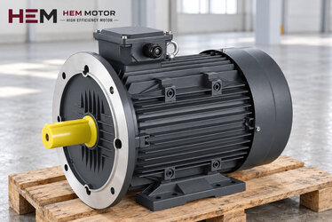
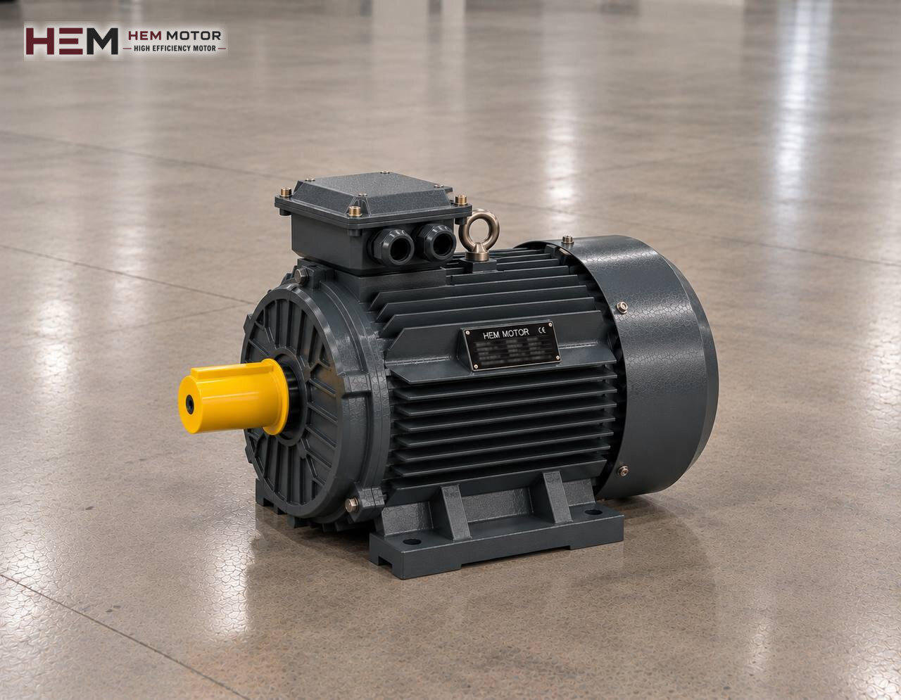
In these fans the motor usually sits at the centre of the casing, in a hub fixed to the guide vanes or to separate support arms. The hub diameter and motor frame must match, so the fan manufacturer specifies the motor by frame size and mounting arrangement. The most common arrangement in cased fans is a motor seated on the hub plate by its feet or by a B5/B14 flange; depending on frame size, B3, B34, B35 and, for vertically installed tower-type fans, V1, V3, V5, V6, V15 versions are also possible. We confirm the flange and shaft size in the order by checking the fan manufacturer's hub drawing. Flange types are explained on the B5 and B14 flange motors page.
The terminal box stays inside the casing; the supply cable is usually routed out through one of the guide vanes or a gland in the casing. The direction the box faces and the cable entry direction should be stated in the order, otherwise the cable may not fit through the vane section.
The motor is cooled by the air the fan moves. If that air is clean and at ambient temperature, this is an advantage. If the fan runs at very low flow for long periods or moves hot, dusty air, the motor's heat dissipation weakens. State the temperature of the conveyed air in your order. An anti-condensation heater can be added for fans that stop and start in humid air, and a PTC/PT100 winding sensor for casings that are hard to reach; both are order options. The IP55 protection of our motors covers dust and water splashes: a corrosive gas stream, a casing cleaned with a hose or an explosive atmosphere is outside that protection. On such a line the fan manufacturer must take extra measures or a special motor must be chosen; please state the situation clearly in your request.
Blade Angle Adjustment and Speed Control
On many vane axial fans the impeller blade angle can be adjusted at standstill. Increasing the angle raises pressure and airflow, and also the power drawn by the motor. If the fan has been readjusted on site, the motor current should be measured afterwards and compared with the rated current on the nameplate.
If airflow has to change during operation, a frequency inverter is the more flexible route. Our three-phase motors can be supplied from a drive. Because fan load drops as the fan slows down, the motor's own cooling fan is enough in most cases; however, if high torque is required at low frequency for long periods, a separately powered cooling fan is considered, and if the line between drive and motor is long, an output filter. Simply add these two details to your request; the topic is covered on the inverter-compatible electric motors page. To avoid approaching the stall limit when speed is reduced, the drive's minimum frequency should be set together with the fan manufacturer.
Where They Are Used and Example HEM Models
Vane axial fans are chosen for air paths with high resistance but a straight layout: mine and tunnel ventilation, paint booth exhaust, long-duct process air, units that blow air across cooling coils. The table below gives a pre-selection seen from the motor side.
| Application | Deciding factor for the motor | To state in the order | Example HEM model |
|---|---|---|---|
| Small-diameter, high-pressure process fan | High tip speed, 2-pole | Shaft end, flange type | 5.5 kW, 2,930 rpm, 132S1-2 cast iron |
| Paint booth exhaust | Paint vapour in the air, filter resistance | Content of the conveyed air, cable exit | 11 kW, 1,465 rpm, 160M-4 cast iron |
| Long-duct ventilation line | Silencer and duct losses, continuous duty | Operating point, inverter use | 22 kW, 1,470 rpm, 180L-4 cast iron |
| Mine or tunnel ventilation | Large impeller inertia, dust and humidity | Starting method, anti-condensation heater | 37 kW, 985 rpm, 250M-6 cast iron |
The motors in the table are meant to give an idea. The right motor is determined by the power the fan draws at its operating point, the speed the impeller needs, the way it mounts to the hub and the condition of the air. In mines where explosive gas may be present, a standard motor cannot be used; this is handled separately in the project.
Protecting the Motor Side During Maintenance
The gap between the guide vanes and the impeller is small. If a blade works loose or dirt builds up on the impeller, the imbalance is passed straight to the motor bearings. Periodic checks should cover blade fixings, impeller cleanliness and bearing noise together. Since reaching the motor often means opening the casing, a PTC sensor that monitors winding temperature remotely reduces surprises between maintenance intervals. Bearing lubrication follows the instructions on the motor nameplate and in the catalogue.
When Sending Your Request
For a quotation it is enough to tell us which machine or installation the fan runs in, the power and speed the impeller requires, the site voltage, how the motor mounts to the hub, the terminal box and cable exit direction, the air temperature and how many units you need. If you photograph the nameplate of your existing motor and send it, we can work out the equivalent from it; see the nameplate guide for how to do this.
Prices are listed on each model's own page in the shop section. You can ask your questions via WhatsApp or by phone using the numbers on the contact page.
Frequently Asked Questions
Does starting a vane axial fan with the damper closed protect the motor?
Usually not. In axial fans the flow separates when airflow drops too far, and in many designs shaft power rises. The damper position during starting should follow the fan manufacturer's instructions.
Since the motor is inside the casing, how can overheating be detected?
Because the motor is hard to see, a PTC or PT100 sensor embedded in the winding is the most practical solution. The sensor is an order option and is connected to a suitable relay in the control panel.
What should I check when replacing the motor of an existing fan?
Besides power and speed, the flange, shaft end, key and the frame size that seats in the hub must match the old motor. The position of the terminal box also affects how the cable passes through the guide vane.
If I increase the blade angle, will I need a bigger motor?
Possibly. As the angle increases, so does the power drawn. Measure the current after adjustment; if it exceeds the nameplate value, the angle is reduced or the motor power is reassessed.