English
 Français
 Türkçe
 Español
 Русский

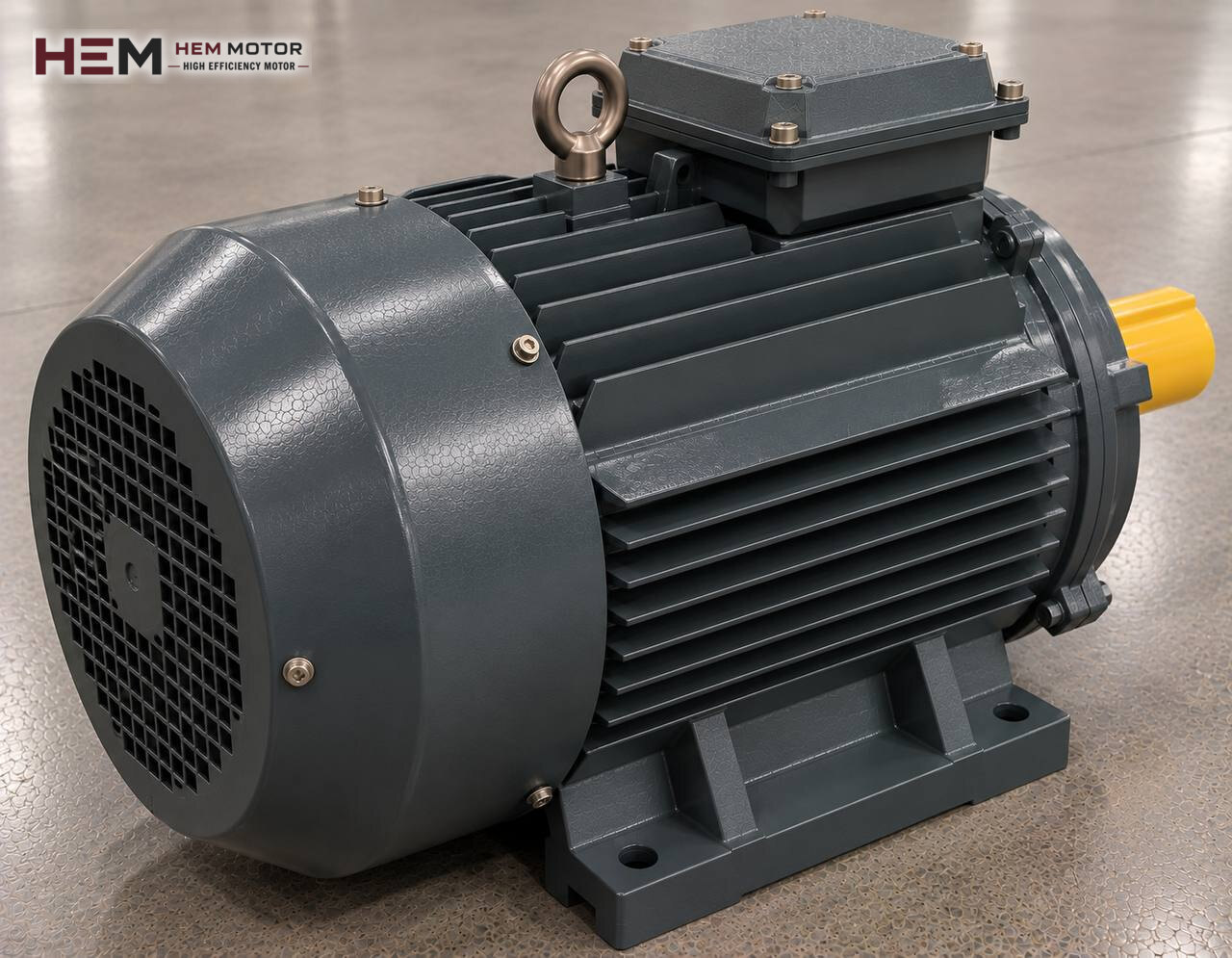
The clay leaving the extruder mouth travels over a roller table as one continuous column; tensioned steel wires divide it into brick or tile lengths. On a wire cutting machine the motors are not there to cut with their own force but to bring the wire to the right place at the right moment. The other machines of the line are on the brick, tile and ceramic production line motors page; this page focuses only on the drives in the cutting section.

How Is the Clay Column Divided by Wire?
On most lines cutting happens in two steps. First the main cutter separates a block of set length from the moving column. An accelerating belt takes this block forward and away from the column. Then, in the multi-wire cutter, a pusher drives the block through a frame strung with tight wires; many green bricks come out in a single stroke.
Because the column never stops, the main cutter is either mounted on a carriage that travels with the column or made as a wired wheel turning at column speed. In both layouts the wire must leave a square cut while the clay is moving; for this the cutter speed is tied to the extruder output speed. On roof tile lines a slicer working on the same principle separates the clay slugs that go to the moulding press.
Drives in the Cutting Section and Their Jobs
Main cutter and synchronised carriage
The carriage moves forward at the same speed as the column, the wire comes down or is pulled sideways, then the carriage returns to its start point. In every cycle the motor accelerates, stops and reverses. On a rotary cutter the motor turns continuously but its speed has to follow the extruder. These drives are usually geared and run from a frequency inverter, using a signal from a measuring wheel riding on the column.
Pusher of the multi-wire cutter
The pusher drives the block through the wire frame and leaves the cut bricks on the discharge belt. On mechanical types a geared motor moves the pusher back and forth through a crank or chain and overcomes the resistance of the wires at each push. On hydraulic types the motor turns a pump set and a cylinder provides the pushing force; in that case the approach on the hydraulic pump electric motors page applies.
Belts, roller table and scrap return
The accelerating belt, the belts towards the setting section and the return belt that takes cut-off ends back to preparation run on small geared motors. The speeds of these belts must match; otherwise the corner of the green brick gets crushed or blocks knock into each other.
Motor Load: Short, Frequent and Reversing Movements
The motors of a wire cutter do not need large power; what strains them is the number of cycles. When the extruder runs fast, the carriage and pusher move many times a minute. Each start leaves heat in the winding, and this heat building up without time to cool is one of the most common reasons small motors fail. Motor power should therefore be judged not only by cutting force but also by movements per hour and the inertia of the moving mass.
Cutting force depends on clay hardness, moisture and the number of wires. When the column gets stiffer or the wires go blunt, the pusher motor current rises. Motors on this kind of cutter usually stay at a few kilowatts; the nameplate of the motor on the existing machine is the most reliable starting point for that same machine.
Synchronisation, Frequency Inverter and Brake
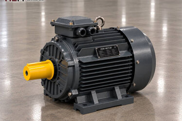
To lock the cutter to the column speed, a frequency inverter is almost always present in this section. HEM three-phase motors are suitable for inverter drive. If the carriage carries load at low speed for long periods, the motor's own fan may not cool it enough and a separately powered fan is added; if the cable between panel and motor is long, an output filter is considered to protect the winding from voltage spikes. Share this information in your request; see the inverter-compatible electric motors page for details.
If the carriage or pusher has to hold at a given point, the machine builder may ask for a brake motor; if you have that need, state it in your order. On machines where the inverter or a mechanical lock does the holding, a standard motor is enough.
Example HEM Models for the Cutting Section
| Drive | Type of motion | Value to check when selecting | Example HEM model |
|---|---|---|---|
| Main cutter or slicer carriage | Reciprocating, tied to column speed | Cycles per hour, gear ratio | 0.75 kW, 1,420 rpm, 80M2-4 cast iron |
| Rotary wire cutter | Continuous, variable speed | Inverter settings, cooling at low speed | 1.5 kW, 1,445 rpm, 90L-4 cast iron |
| Multi-wire cutter pusher (mechanical) | Pulsating push, frequent starts | Number of wires, clay hardness | 3 kW, 1,450 rpm, 100L2-4 cast iron |
| Hydraulic pusher pump set | Pump drive | Pump flow and pressure | 4 kW, 1,450 rpm, 112M-4 cast iron |
The models in the table are examples; the final choice is set by the machine load, the required speed, the mounting arrangement and the operating conditions.
The Motor Among Clay, Water and Wire Debris
The cutting section is a wet place. On some lines water or a fine oil is sprayed on the wire so it does not stick to the clay; clay scraps from cutting pile up under the belts. Our motors have IP55 protection, but hosing down or spraying water directly is outside the scope of this protection. If the motor sits close to the spray zone, the machine builder needs to fit a shield or a special motor should be chosen; state this in your order.
On motors connected to a gearbox, flange B5 or B14 and foot-and-flange B34/B35 frames are common; drives sitting on a base often use the foot-mounted B3 frame. Which arrangement can be selected depends on frame size; vertical V1, V3, V5, V6 and V15 arrangements are also available, and we confirm flange and shaft dimensions together at order. A PTC/PT100 sensor for watching winding temperature and an anti-condensation heater against moisture during long stops are order options. For geared drives, the electric motors for gear reducers page also helps.
Information for a Cutter Motor Request
For quick matching, send us the machine type (main cutter, rotary cutter, multi-wire pusher, belt), the required power and speed, the supply voltage, the mounting arrangement and the number of units. A nameplate photo of the existing motor answers most questions on its own; for geared drives it helps to add the gearbox nameplate too.
You can browse the models in our electric motor shop; the current price is shown on the product page. Our WhatsApp and phone details are on the contact page.
Frequently Asked Questions
Why does the cutter carriage motor heat up quickly?
If the carriage accelerates, stops and reverses every cycle, the motor draws starting current again and again. As the cycle count rises, heat accumulates. Inverter ramp settings, gear ratio and motor power should be reviewed together.
If bricks are cut at an angle, is the motor the problem?
Usually not. A slanted cut shows the cutter is not following the column speed exactly; slip of the measuring wheel, inverter settings or mechanical play should be checked. The motor is the cause only if it cannot deliver the required acceleration.
Why does the pusher motor current change during the day?
As clay moisture and hardness change, the resistance the wires meet changes too. Blunt or slack wires increase the pushing force. If the current stays above the nameplate value, check the wires and clay preparation first.
Can a single-phase motor be used in the cutting section?
On small workshop-type cutters where there is no three-phase supply, our single-phase motor range from 0.18 to 5.5 kW can be considered. On industrial lines running in sync through an inverter, a three-phase motor is the better fit.