English
 Français
 Türkçe
 Español
 Русский

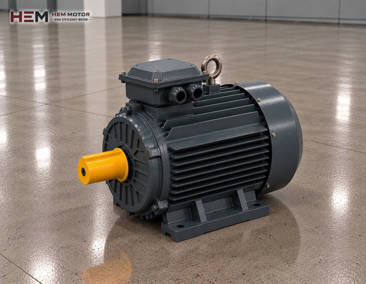
Green bricks leaving the cutter travel one by one on a belt; before they can enter the kiln they must first be placed on drying racks and, once dry, set onto kiln cars in a fixed pattern. The setting and stacking system that builds this pattern is the part of the line with the most moving axes. The general layout of the line is on the brick, tile and ceramic production line motors page; here we talk only about the motors that move this system.

Where Does the Setting System Move the Bricks?
In a classic tunnel kiln plant, bricks are set twice. In the first step, wet product from the cutting section is loaded onto drying racks or dryer cars. When the racks are full, a lift and a finger car push them into the dryer. When dry product comes out, the second step begins: the setting machine lines up the bricks, groups them and places them on the kiln car layer by layer, leaving flue gaps between them.
When the fired product leaves the kiln, the process runs in reverse. The unloading machine takes packs off the car, the stacking unit seats them on a pallet and sends them on to strapping or stretch wrapping. So the same line holds many drives for loading, transfer and unloading that look alike but carry different loads.
Moving Parts, Axis by Axis
Grouping belts and turning table
Before setting, bricks are brought side by side, the gap between them is adjusted and, if needed, a row is turned 90 degrees. Short belts running at independent speeds do these jobs. The motors are small, geared and accelerated and slowed by an inverter; ramps are kept gentle so the product does not tip over.
Gantry bridge and lifting axis
The gripper head takes a layer of bricks from above, lifts it, carries it along the bridge over the car and lowers it. The horizontal travel axis accelerates and stops a mass with inertia over a short distance. The vertical axis holds the load in the air; a holding brake is needed on this axis so the head does not drop when power is lost. If a brake motor is needed, state it in your order. In some plants these axes are handled by an industrial robot or servo drives; those drives are outside the scope of a standard induction motor.
Transfer car, lift and kiln car pusher
The transfer car that moves a loaded car from track to track carries a heavy mass slowly and must stop at a precise position. The drying rack lift raises the load vertically; holding is again solved with a brake or a mechanical lock. The pusher that drives the train of cars into the kiln is hydraulic in most plants: the motor turns the pump and a cylinder supplies the pushing force. For this type, the sizing logic on the hydraulic pump electric motors page applies.
What Strains the Motor in This System?
None of the drives in the setting section runs continuously at full load; all of them work in a cycle of short moves, waits and restarts. Heating is set by the number of starts per hour and the inertia of the mass being accelerated. Accelerating a loaded kiln car or a laden gripper head takes much more current than holding the same power at constant speed.
Precise stopping is a load of its own. To hit the position, the motor approaches at low speed and creeps through the last centimetres. During this time its own fan turns slowly, so cooling weakens. When choosing motor power, the nameplate of the existing drive, the gear ratio and the cycle time should be considered together; in similar plants most of these axes do not exceed a few kilowatts, while heavy drives such as the transfer car and pusher can go higher.
Speed Control, Positioning and Sensors
For smooth acceleration and precise stopping, almost every axis in this system is connected to a frequency inverter. HEM three-phase motors can be used with an inverter. If the slow approach lasts long and the motor delivers full torque during it, a separately powered cooling fan may need to be added. Because the cables from panel to motor run along the gantry, a dv/dt or sine filter at the output is taken into consideration. It is enough to write these conditions at the quotation stage; the inverter-compatible electric motors page gives details on inverter operation.
Position information usually comes from an encoder or proximity sensors fitted to the axis; this hardware is within the machine builder's scope. On the motor side, a PTC/PT100 sensor monitoring winding temperature is useful on axes with frequent starts and can be added as an order option.
Example HEM Models for Setting and Stacking
| Axis or drive | Operating pattern | Value to check first | Example HEM model |
|---|---|---|---|
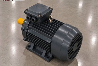
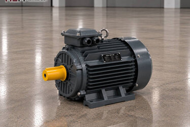
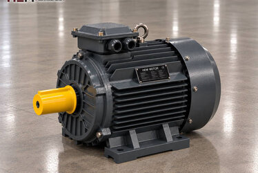
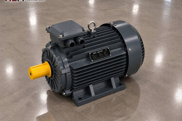
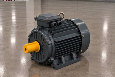
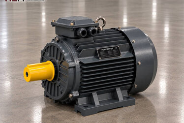
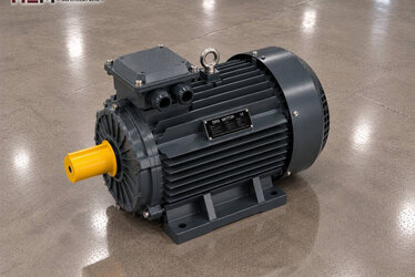
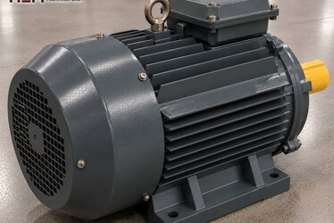
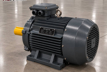
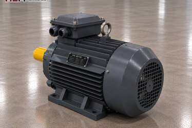
| Grouping and intermediate belts | Short, inverter-accelerated | Matching of belt speeds | 1.1 kW, 1,445 rpm, 90S-4 cast iron |
| Gantry bridge travel | High inertia, frequent stop-start | Mass carried, cycles per hour | 2.2 kW, 1,450 rpm, 100L1-4 cast iron |
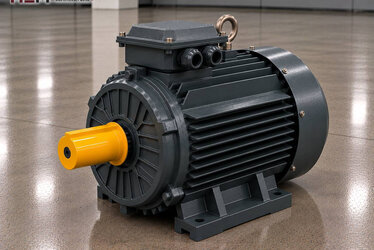
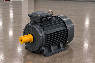
| Transfer car | Heavy load, precise stop | Car weight, gear ratio | 5.5 kW, 1,460 rpm, 132S-4 cast iron |
| Hydraulic kiln car pusher | Pump drive, intermittent | Pump flow, pressure, push time | 7.5 kW, 1,460 rpm, 132M-4 cast iron |
These pairings are meant as a guide; the final choice is made by considering machine load, required speed, mounting and operating conditions together.
Dust, Temperature and Mounting Conditions
In the section where dried bricks are set, fine clay dust hangs in the air and settles between the motor fins. At the kiln exit, the air is warm and the cars are hot. Our motors come with IP55 protection and class F insulation; this is enough for the normal dust of this section, but regular cleaning is essential to keep cooling going. For a motor to be placed directly in front of the kiln mouth or right above a hot car, state the ambient temperature in your order.
On gantry and car drives, the motor is often flange-connected to a gearbox; B5, B14 and foot-and-flange B34/B35 frames are common in these layouts, and B3 is used for drives on a base. Depending on frame size, shaft-down or shaft-up vertical versions (V1, V3, V5, V6, V15) are also offered; we confirm flange and shaft dimensions with you at order. The electric motors for gear reducers page helps with gearbox matching, and the conveyor belt electric motors page helps with moving belts.
When Asking About a Setting System Motor
Your request should include: which machine and axis the motor is for (belt, bridge, lifting, transfer car, pusher), the required power and speed, the site voltage, the mounting arrangement and the quantity. If you add a photo of the old motor's nameplate, finding an equivalent is quicker; on braked axes, include the brake details too.
You can find all models on the buy electric motors page and see the current price on the product page. To reach us by WhatsApp or phone, see our contact page.
Frequently Asked Questions
Can a standard motor be fitted to a lifting axis?
On an axis holding a load in the air, the head or rack must not drop when power is lost. This holding must be provided by a brake or a mechanical lock; if a brake motor is wanted, state it in your order.
Why does the transfer car overshoot its stopping point?
If a heavy car approaches at high speed, the stopping distance gets longer. The inverter deceleration ramp, the position of the approach sensor and wheel slip on the rail should be checked together; motor power is usually not the cause.
Which frame is preferred for setting machine motors?
Aluminium frames can also be used on small belt motors; cast iron frames are chosen more often for vibrating, heavily loaded gantry and car drives. The decision depends on the gearbox flange and mounting location.
How do I size the kiln car pusher motor?
On a hydraulic pusher the motor turns the pump; the power needed depends on pump flow, system pressure and push time. On mechanical chain pushers, the total weight and friction of the car train are decisive. In both cases the existing motor nameplate is the soundest starting point.