English
 Français
 Türkçe
 Español
 Русский
 العربية

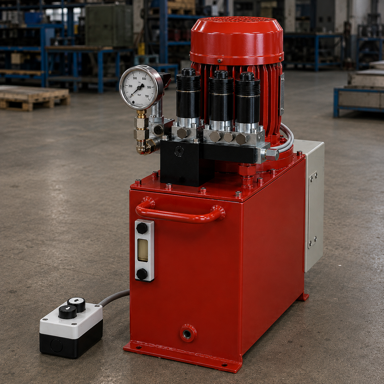
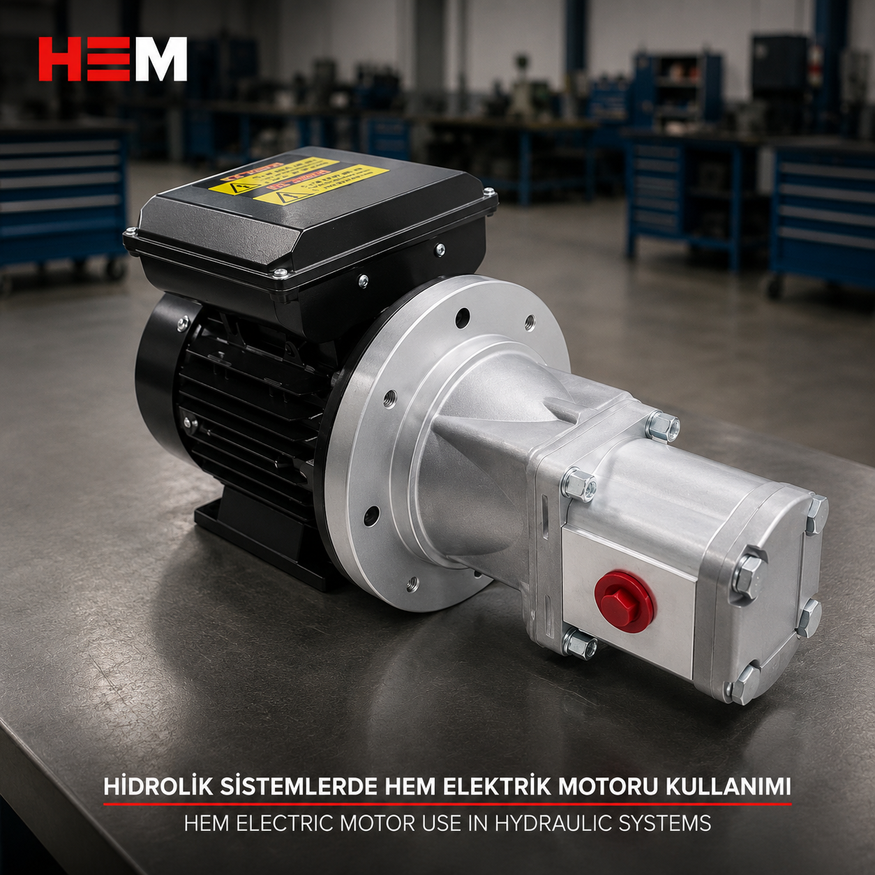
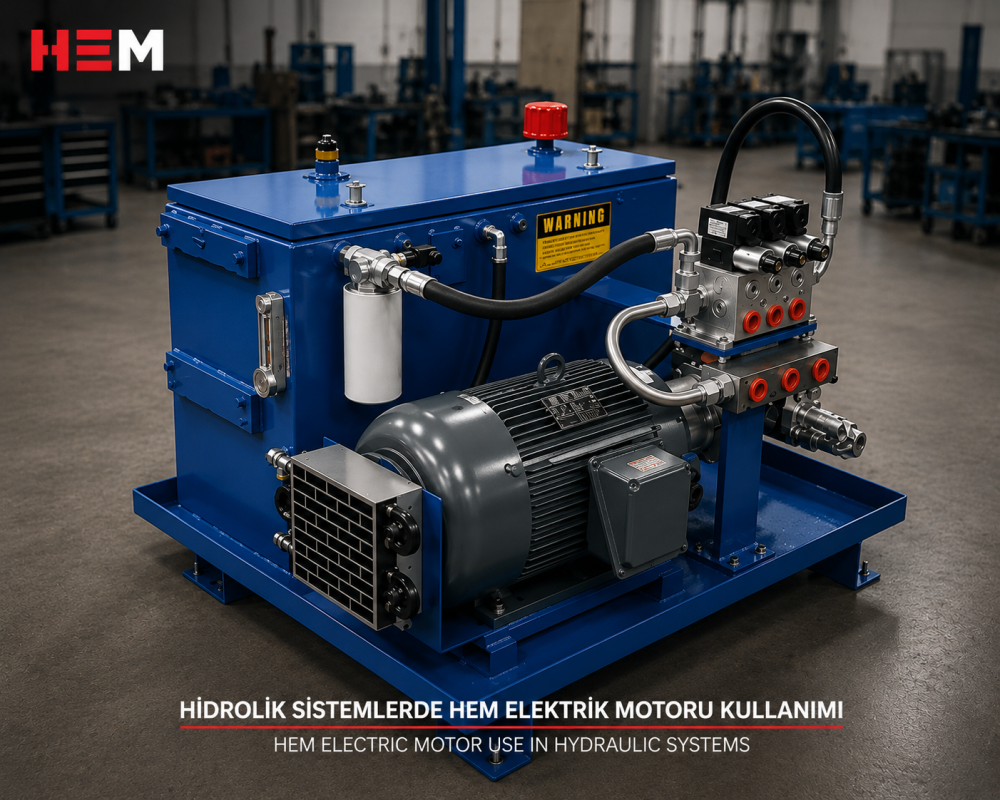
In a hydraulic power unit the electric motor has one job: to turn the pump shaft at a steady speed. The force that pushes the cylinder, closes the mould or lifts the load is produced not by the motor but by the oil the pump delivers and by the valve block. This page covers the three-phase motor that drives that pump; for the general picture of all pump types see the Pump Electric Motors page.

The motor supplies rotation, the oil carries the force
The electrical part of the unit only provides mechanical power. The pump converts that power into flow; when the flow meets resistance, pressure rises. With no resistance ahead of the cylinder, the pump moves a lot of oil at low pressure and the motor runs easily. Once the press platen touches the part, pressure climbs, the shaft power needed for the same flow increases and the motor current goes up.
That is why the kW figure on the motor nameplate does not tell you the machine's force in tonnes. A slow cylinder delivers a given force with a small motor; a fast cylinder needs a bigger one for the same force. Selection always comes down to two questions: how many litres of oil, and at what pressure?
From flow and pressure to motor power
For preliminary sizing an approximate relation is enough:
P [kW] ≈ Q [l/min] × p [bar] / (600 × η)
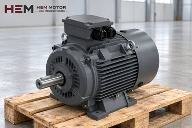
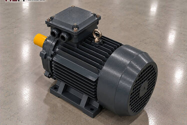
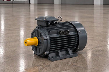
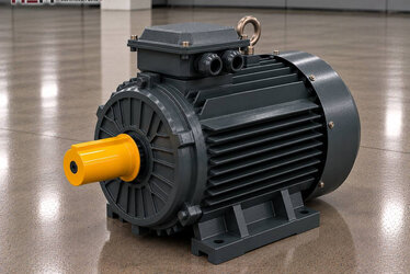
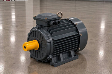
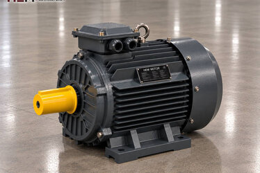
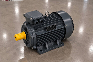
Here η is an assumption for the overall efficiency of the pump and drive train; for gear pumps 0.85 can be taken as an example. Example: a circuit requiring 20 litres of oil per minute at 160 bar gives 20 × 160 / (600 × 0.85) ≈ 6.3 kW. The next standard rating, 7.5 kW, for instance the 132M-4 cast iron motor (7.5 kW, 1,460 rpm), is a reasonable starting point for this calculation.
Flow itself depends on speed: the volume the pump delivers per revolution (cm³/rev) multiplied by speed and divided by 1,000 gives litres per minute. A 14 cm³/rev pump at 1,460 rpm delivers about 20 l/min; the same pump on a 2-pole motor delivers close to twice the flow but needs correspondingly more power. The calculation is only a first estimate; the exact value comes from the pump manufacturer's curve and the machine cycle.
Speed and starting for gear, vane and piston pumps
Gear pump: Fixed displacement, simple and robust. Most units run it with a 4-pole (1,500 rpm class) motor. Because its flow is proportional to speed, changing the motor also changes the cylinder speed.
Vane pump: Runs more quietly; variable displacement versions reduce flow automatically as pressure rises, limiting the load on the motor. To make sure the vanes extend properly, do not go below the minimum speed stated by the pump manufacturer.
Piston (axial) pump: Preferred for high-pressure and continuous-duty circuits. With pressure-compensated types the motor power can be chosen on the assumption that maximum pressure and maximum flow are not demanded at the same time; confirm this assumption with the pump supplier.
A well-designed unit starts unloaded, dumping oil back to the tank. In that case star-delta or a soft starter is usually sufficient. If the pump has to start against pressure, the motor's starting torque must be checked separately.
Connecting to the pump: B35, B5, coupling and bell housing
In horizontal units the motor usually sits on a base by its feet and is bolted to the bell housing by its front flange; this is the B35 foot-and-flange motor arrangement. In units standing upright on the tank lid the motor is carried by its flange alone: B5 or vertical V1 is used; see flange-mounted motors for the options.
Inside the bell housing there are two coupling halves: one fits on the motor shaft, the other on the pump shaft. Since the bell housing transfers the motor flange spigot to the pump flange, it largely prevents shaft misalignment. When ordering, compare the flange type, shaft diameter and key size with the bell housing on the pump side. Depending on frame size, B3, B5, B14, B34, B35 and V1/V3/V5/V6/V15 arrangements are offered; flange and shaft dimensions are confirmed with the order.
Cycles in presses, injection and lifting machines
What hydraulic machines share is a load that changes all the time. A press cycle runs through rapid approach, pressing, pressure holding and return in succession. A waste baling press works with long compaction strokes; a plastic injection moulding machine needs different flows during mould closing, injection, holding pressure and cooling time.
| Hydraulic application | How the pump works | What to check when choosing the motor | Example HEM model |
|---|---|---|---|
| Workshop and deep-drawing press | High flow on approach, high pressure while pressing | The step with the largest flow × pressure, cycles per hour | 132M-4 · 7.5 kW |
| Waste and scrap baling press | Long compaction, filling pauses in between | Compaction time, dusty environment, heating | 200L-4 · 30 kW |
| Plastic injection moulding machine | Flow changing step by step, low load during cooling | Variable displacement pump or speed control, continuous duty | 160L-4 · 15 kW |
| Lifting platform and goods lift | Pumps only on the way up, oil returns by gravity on the way down | Starts per hour, starting method | 112M-4 · 4 kW |
| Clamping and test unit | Short pumping, long pressure holding | Idle running time, use of an accumulator | 112M-4 · 4 kW |
The models in the table are examples; the final choice depends on machine load, required speed, mounting and operating conditions.
Idle running, heating and winding protection
In many hydraulic machines the motor idles for a large part of the cycle: the pump sends oil to the tank at low pressure. Current drops during this time but the motor keeps turning; continuous running is preferred to frequent stop-start because every start heats the winding. In lifting arrangements, however, the motor restarts for every movement; always state the number of starts per hour.
Heat comes from two sources. The first is the winding: short pressure peaks can push the motor above its rated power, and repeated peaks build up heat even when the average load stays low. The second is the unit: a motor sitting on top of a hot oil tank draws its cooling air from a warmed environment. Keep the space in front of the fan cover clear and allow for ventilation in closed cabinets.
PTC or PT100 winding sensors and an anti-condensation heater are available as order options. If you want to adjust the pump speed with a frequency inverter, our three-phase series are suitable; if the motor will run at low speed with full torque for long periods an external fan, and if the cable between drive and motor is long a dv/dt or sine filter, are considered. Details are on the inverter-compatible motors page.
What information is needed for a quotation?
For a fast and accurate quotation, send us: the machine type (press, injection, lifting, etc.), the required motor power (kW) or the pump's flow and pressure, speed (rpm), supply voltage, mounting type (B35, B5, V1) and quantity. If you are replacing an existing motor, send a photo of the motor nameplate; we will find the equivalent from it.
Models delivered from stock are available in our electric motor shop, and the current price is shown on each product page. If you are unsure about the bell housing and coupling dimensions, share the pump details via our contact page.
Frequently Asked Questions
Should a hydraulic unit use a 2-pole or a 4-pole motor?
Most gear and vane pumps are designed for the 1,500 rpm class, which is why 4-pole motors are common. If the pump is to run in the 3,000 rpm class, check the manufacturer's data to confirm that it allows this speed.
Can I find the motor power from the press tonnage?
Not directly. Tonnage relates to cylinder area and pressure, whereas motor power is set by pressure plus the flow that determines cylinder speed. Pin down flow and pressure first, then use the approximate formula.
Why does the motor draw current even when idling?
Even in the unloading position the pump keeps turning and pushes oil to the tank; the motor draws magnetising current plus enough to cover friction losses. This is normal; for long pauses the machine builder can add logic that stops the motor.
Can I mount the motor vertically on the tank lid?
Yes, the flanged V1 arrangement is meant for this. The shaft points down and the motor connects to the pump through the bell housing. State vertical mounting and the bell housing flange size in your order.
My existing motor runs hot as if it were undersized; what should I do?
First check whether the pressure setting matches the pump and machine values and whether the fan is getting clean air. Then send us the nameplate data and cycle time; a higher rating or a version with winding sensors can be assessed together.