English
 Français
 Türkçe
 Español
 Русский
 العربية

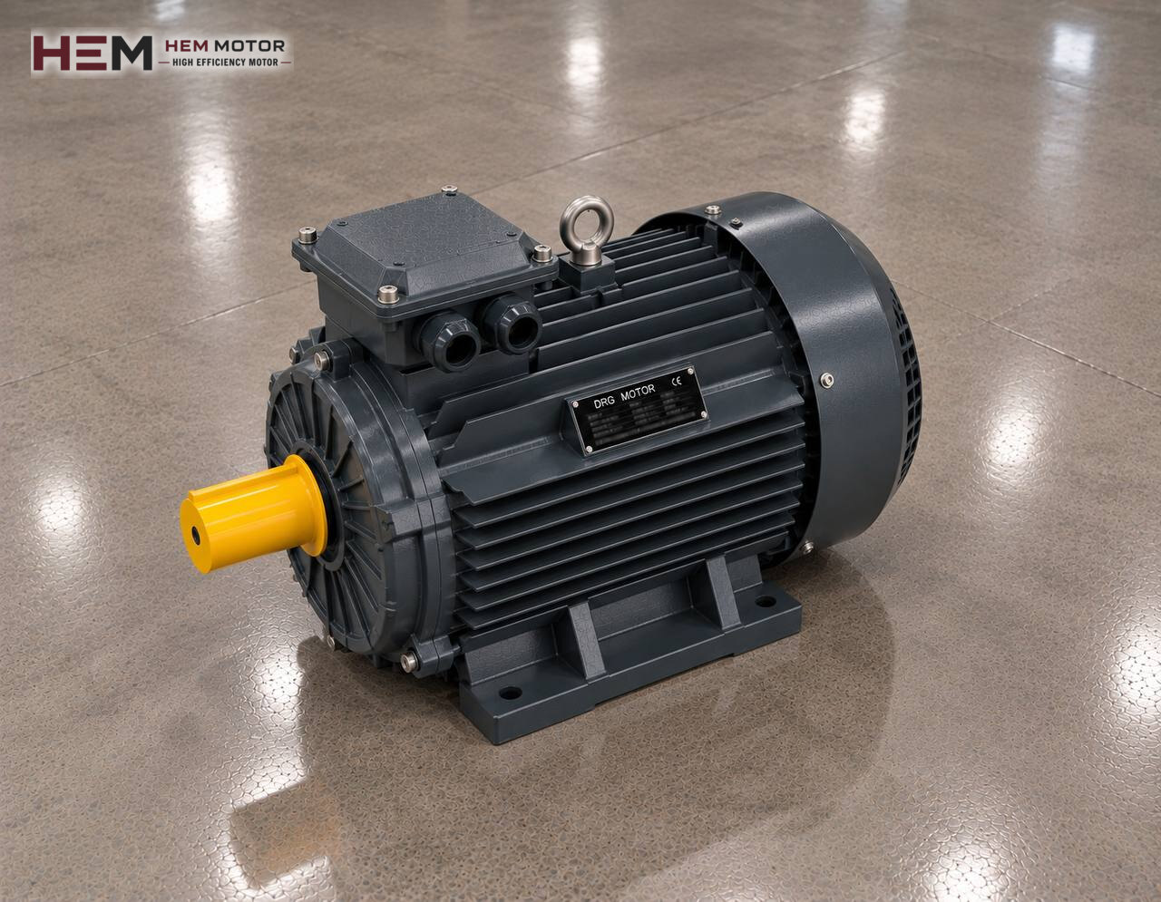
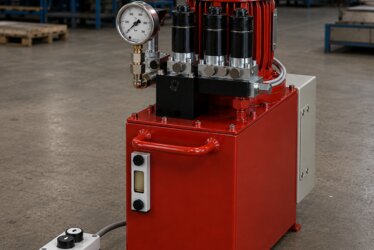
A hydraulic power unit is a self-contained package placed next to a press or machine tool, combining the oil tank, motor-pump group, valve block, filter and often an oil cooler. This page covers the electric motor inside that package: where it sits on the tank, the difference between horizontal and vertical layouts, double-pump arrangements, heat balance and the unit's operating scenarios. Sizing the pump power from flow and pressure is explained in detail on the hydraulic pump electric motors page; the framework for all pump types is on the Pump Electric Motors page.

The Unit Is a Package: Where Does the Motor Sit?
In a power unit the motor is attached to the cover plate on top of the tank or to a separate base beside the tank. Between motor and pump there is a bell housing and two coupling halves; the bell housing carries the connection and keeps the two shafts on the same axis. The motor does not go into the oil: even if the pump is immersed, the motor stays outside the tank, on the side cooled by air.
The tank cover carries the motor but is also a vibrating surface. A thin sheet-metal cover can amplify motor and pump vibration and make the tank ring like a loudspeaker. That is why in good units the motor-pump group sits on rubber mounts or a damping intermediate plate, and flexible hoses are used on the suction and return lines.
Horizontal and Vertical Layout: B35, V1 and Immersed Pump
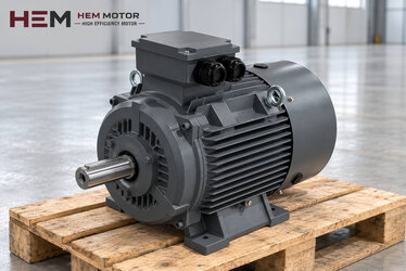
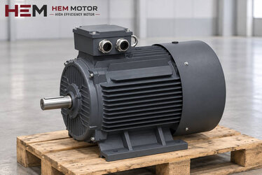
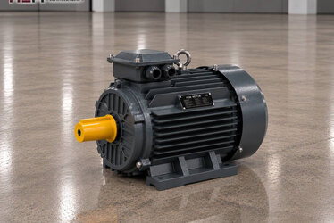
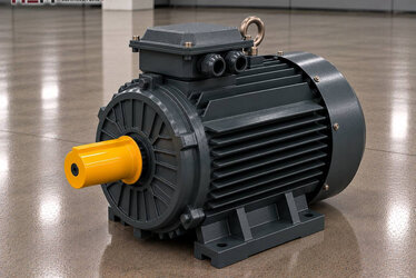
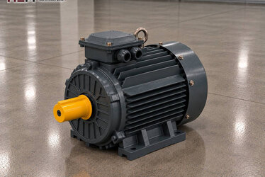
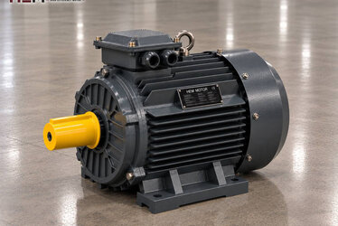
In a horizontal unit the motor stands on its feet on the base or cover and is bolted to the bell housing by its front flange. This is the foot-and-flange B35 motor arrangement. The pump is outside the tank; it is easy to reach for maintenance, but the suction line gets longer.
In a vertical unit the motor sits on its flange on top of the cover with the shaft pointing down; the bell housing passes through the cover and the pump stays in the oil. This is V1 mounting; it saves space, and the oil in the tank partly muffles pump noise. In vertical mounting the bearings carry the load along the shaft axis; this must be stated in the order when selecting the motor. For details see our article on vertical mounting V1/V5.
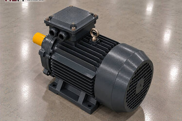
Depending on the frame, B3, B5, B14, B34, B35 and V1/V3/V5/V6/V15 arrangements are offered; flange and shaft dimensions are confirmed in the order against the bell housing maker's dimensions.
Double Pump, Accumulator and Variable Displacement
In many units two pumps are mounted one behind the other on the motor shaft. The large pump feeds the fast approach at low pressure, the small pump the high-pressure pressing step; when pressure rises, the large pump is opened to the tank through an unloading valve. The purpose is to prevent the motor from seeing high flow and high pressure at the same time. Motor power is chosen according to whichever of the two steps needs more power.
In units with an accumulator, the pump fills a gas-loaded vessel; short bursts of high flow are covered by the accumulator. This lets the motor be sized for the average load, but it runs at full load while charging.
In units using a pressure-compensated variable displacement pump, the pump reduces flow by itself as pressure approaches the set value. The motor then sees full load for short periods and low load for long periods. Speed control can also be applied to such a unit: our three-phase series can be driven by a frequency inverter, and whether a separate fan is needed for long running at low speed with full torque, or a dv/dt or sine filter for long cables, is discussed in the order. See inverter compatible electric motors.
Oil Temperature, Cooler Fan and Motor Heat
In a power unit, losses in the pump, valves and pressure drops pass into the oil as heat. As the oil warms, so do the tank surface and the cover; the motor on the cover draws its cooling air from just above this warm surface. In units squeezed inside a closed machine body, leaving enough space in front of the motor's fan cover is as important as choosing the motor.
Most units have an air-cooled heat exchanger to cool the oil. The fan of this exchanger may be turned by a separate low-power motor; our small aluminium frame models are a suitable starting point for it. With a water-cooled exchanger, a circulation pump is turned by a small motor.
For machine builders who want to monitor winding temperature, PTC or PT100 sensors are an order option. The enclosure is IP55 and insulation class F. For units that stand still at night in a humid workshop, an anti-condensation heater can be ordered.
The Unit's Operating Scenario and Starting
A unit is run in one of two ways. In the first, the motor turns throughout the shift and the pump unloads oil to the tank at low pressure when not needed. In the second, the motor starts only when movement is required; lifting platforms and some clamping arrangements work this way. In the second scenario, the number of starts per hour is the main value that determines motor heating and should be stated at the quotation stage.
In a unit designed to start unloaded, star-delta starting is common. Our catalogue models from 4 kW upwards are rated 400/690 V (Δ/Y) and suit this method on a 400 V supply; at smaller outputs the rating is 230/400 V, so direct-on-line starting or a soft starter is used. Because viscosity is high when the oil is cold, current may stay high for longer during the first starts; in winter a tank heater reduces this difference.
Example Motors by Unit Type
| Unit type | How the motor works | What to watch when selecting | Example HEM model |
|---|---|---|---|
| Compact clamping and test unit | Short pumping, long waiting | Number of starts, layout on the tank | 4 kW aluminium, 112M-4 |
| Vertical (V1) machine tool unit | Immersed pump, running all shift | Vertical mounting, axial load | 11 kW cast iron, 160M-4 |
| Double-pump press unit | Fast approach and high-pressure step | The step needing the most power | 22 kW cast iron, 180L-4 |
| Central hydraulic station | Continuous operation feeding several machines | Heat balance, starting method | 45 kW cast iron, 225M-4 |
The models are examples; the final choice depends on the unit's load, required speed, mounting and operating conditions. If a motor is being replaced, the power and speed on its nameplate are the first place to look.
Information We Need for a Power Unit Motor
In your request, state the machine or unit type, motor power (kW) or the pump's flow and pressure, speed (rpm), supply voltage, mounting arrangement (B35, B5 or V1), bell housing flange size and quantity. If the unit starts and stops often, add the number of starts per hour. Sending a photo of the existing motor's nameplate makes it easier to find an equivalent: send the motor nameplate.
Models and current prices are on the buy electric motors page. WhatsApp and phone details are on the contact page.
Frequently Asked Questions
Does the motor touch the oil in a vertical unit?
No. In a vertical unit only the pump and the lower part of the bell housing are in the oil; the motor stands in the air above the cover and is cooled by its own fan.
In a double-pump unit, which pump should the motor power be based on?
Not on a single pump, but on the step of the cycle that needs the most power. The pressure at which the large pump unloads and the maximum pressure of the small pump are assessed together.
The unit tank gets very hot; would a bigger motor solve it?
Usually not. Heating is most often caused by oil circulating needlessly through valves with a pressure drop, or by an undersized cooler. Check the hydraulic circuit and cooler first.
Do you supply the bell housing between motor and pump?
This page covers the motor only. We confirm the flange and shaft dimensions on the motor side of the bell housing in the order; we recommend selecting the bell housing and coupling together with the unit builder.