English
 Français
 Türkçe
 Español
 Русский
 العربية

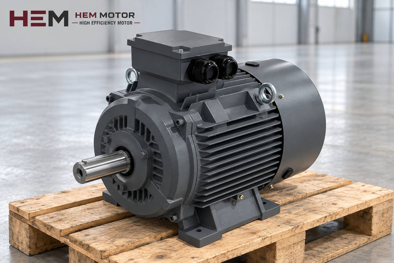
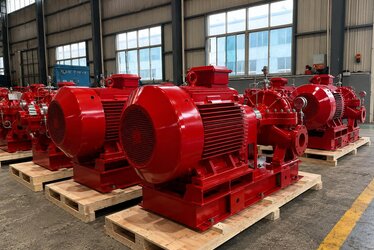
In an end-suction centrifugal pump it is the impeller that moves the water, but the electric motor decides how fast that impeller turns, where on its curve the pump operates and how much current is drawn from the grid at start-up. This page explains how to select the three-phase asynchronous motor that drives a horizontal centrifugal pump and how it is connected to the pump. For an overview of all pump types, see our Pump Electric Motors main page.

Baseplate with Coupling or Close-Coupled: Two Arrangements
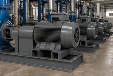
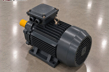
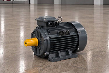
Horizontal centrifugal pumps are joined to the motor in two different ways. In the first, pump and motor sit separately on the same steel baseplate and the two shafts are linked by a flexible coupling. The motor is foot-mounted (B3); because the pump has its own bearing housing, the axial thrust of the impeller is not carried by the motor bearings.
The second arrangement is close-coupled (monobloc): the pump volute is bolted to the motor flange and the impeller sits directly on the motor shaft or on a short extension fitted to it. With no baseplate and no coupling, space is saved and alignment work disappears. In return, the hydraulic thrust and the weight of the impeller are carried by the motor bearings; flange and shaft end must match the pump manufacturer's dimension drawing. This connection uses a B5 or a foot-and-flange B35 frame; details on our flange-mounted motors page.
How the Pump Curve and Duty Point Affect the Motor
Every centrifugal pump has a characteristic curve showing head against flow at constant speed. The plant's pipes, valves and the level difference between two tanks draw their own system curve. Where the two curves cross is the duty point; the motor delivers exactly the power the pump needs to move water there.
In most radial-impeller pumps the shaft power rises as flow increases. The motor is therefore assessed not only at the design point but at the furthest right-hand point the pump can actually drift to. A pump filling an empty line for the first time, or one feeding a burst pipe, runs out to the end of its curve and the motor draws excess current. If the liquid is denser than water, power rises in the same proportion. The power line in the pump manufacturer's curve set is the most reliable figure for sizing the motor.
Adjusting Speed Instead of Throttling a Valve
The traditional way to reduce flow is to throttle the valve on the discharge line. The system curve becomes steeper and the pump delivers less water; but part of the pressure it produces turns into heat at the valve, and the pump may move away from its best efficiency point.
When speed is lowered with a frequency inverter, the pump curve itself moves down. According to the affinity laws, flow changes in proportion to speed, head with the square of speed and shaft power roughly with the cube of speed. That is why speed control is preferred on lines whose demand varies through the day. In systems with a large static head, the pump stops delivering below a certain speed; the minimum frequency is set at the design stage.
Our three-phase series are suitable for speed control with a frequency inverter; for long periods at low speed with full torque, a separate cooling fan may be needed. If the cable between drive and motor is long, a dv/dt or sine filter is considered; state these conditions in your order. Details: inverter-compatible electric motors.
2 Poles or 4 Poles?
A pump impeller is designed for a specific speed; the motor speed must match the speed on the pump's nameplate. On a 50 Hz supply, two-pole motors belong to the 3000 rpm synchronous speed class and four-pole motors to the 1500 rpm class, and they run slightly slower under load. In the 5.5 kW class, for example, the 132S1-2 has a rated speed of 2,930 rpm and the 132S-4 1,460 rpm. At the same power, the rated torque of the four-pole motor (36 Nm) is about twice that of the two-pole one (17.9 Nm).
Running a pump at half speed cuts its flow to roughly one half and its head to one quarter. A motor chosen for a 2-pole pump therefore cannot be replaced by a 4-pole one; the reverse overloads the impeller and the seal. As a general tendency, small pumps needing high head run with 2-pole motors, while large-flow pumps or those with difficult suction conditions run with 4-pole motors. The final decision belongs to the pump manufacturer's curve.
NPSH and the Role of Speed on the Suction Side
NPSH expresses the pressure margin needed at the pump inlet so that the liquid does not vaporise. The value the plant provides (NPSHa) depends on suction lift, losses in the suction pipe and liquid temperature; the value the pump requires (NPSHr) is given in its curve set. If NPSHa does not stay above NPSHr by a sufficient margin, cavitation begins: the pump sounds as if gravel were tumbling inside, flow drops and the impeller surface is eroded.
What matters for the motor is that NPSHr increases with speed. Delivering the same flow with a smaller 2-pole pump can make the suction condition harder.
Coupling Alignment and First Start-Up
On coupled pumps, the motor shaft and the pump shaft must be on the same axis, both in parallel and in angle. A flexible coupling tolerates small misalignments but does not remove them; the vibration they cause wears first the coupling insert, then the bearings and the mechanical seal. Permitted values are given in the coupling and pump manufacturers' documents.
- All four motor feet must sit fully on the baseplate; a foot with a gap (soft foot) is corrected with shims before alignment with dial gauges or a laser begins.
- Suction and discharge pipes must not hang their weight on the pump; pipe strain spoils the alignment later.
- On pumps handling hot liquid, alignment is checked again once operating temperature is reached.
- Direction of rotation is compared with the arrow on the volute; if reversed, two supply phases are swapped. The pump is never run dry.
The Motor on Hot Water and Circulation Lines
Circulation pumps in heating, process heating and cooling water circuits run for months without stopping; what counts is winding and bearing temperature in continuous operation. If the cooling air reaching the motor in a boiler room is hot, state this in your order.
Heat from the hot liquid travels towards the motor through the volute and shaft. In the coupled arrangement this effect is weak because the pump's bearing housing sits in between; in the close-coupled arrangement the motor's front end shield and bearing receive more heat. In damp pump rooms with seasonal shutdowns, condensation can form in the winding; an anti-condensation heater and a PTC/PT100 winding sensor are order options. For building services, the HVAC sector motors page is also a useful guide.
Motor Matching by Pump Arrangement
| Pump arrangement | Motor connection | Points to check | Example HEM model |
|---|---|---|---|
| End-suction pump coupled on a baseplate | Foot-mounted B3 motor, flexible coupling | Shaft height, alignment, power at end of curve | 15 kW, 160M2-2 cast iron (2,945 rpm) |
| Close-coupled pump | Flanged B5 or B35 motor | Flange and shaft end size, bearing load | 5.5 kW, 132S1-2 aluminium (2,930 rpm) |
| Hot water circulation pump | B3 motor, coupling | Continuous duty, ambient temperature, condensation | 5.5 kW, 132S-4 aluminium (1,460 rpm) |
| Large-flow end-suction pump | B3 motor, spacer coupling | NPSH margin, starting method, 4 poles | 30 kW, 200L-4 cast iron (1,475 rpm) |
The models in the table are examples; the final choice depends on the pump curve, required speed, mounting arrangement and operating conditions. Flange and shaft dimensions are confirmed with the order.
What to Send Us Before Ordering
To match the right motor quickly, tell us: the pump type and the machine or plant it serves, required power (kW), speed (rpm), supply voltage, mounting arrangement (B3, B5, B35…) and quantity. A photo of the pump nameplate and of the removed motor's nameplate is the shortest route; our nameplate photo page explains how.
All aluminium and cast iron frame models are listed with prices in the buy electric motors section; motors delivered from stock ship from our warehouse in Türkiye. For project questions, reach us via the contact page.
Frequently Asked Questions
Can a standard motor be fitted to a close-coupled pump?
Yes, if the flange and shaft end match the size the pump requires. Some close-coupled pumps use an extended or specially machined shaft; in that case a standard shaft may not fit. Share the pump's dimension drawing or the old motor's nameplate with your order.
Is it right to lower motor current by throttling the valve?
Current falls because flow falls; but as the pump approaches the left end of its curve, heating and vibration in the pump can increase, and part of the pressure is lost at the valve. If flow changes constantly through the day, speed control is a better solution.
What happens if I connect a 1,450 rpm motor to a 2,900 rpm pump?
The pump delivers roughly half the flow and a quarter of the head; in most plants the water does not reach the required point. Always choose motor speed according to the pump nameplate.
Does cavitation affect the motor too?
It does not affect the winding directly, but vibration reaches the motor bearings through the shaft and coupling. When cavitation noise is heard, the suction line and NPSH margin should be examined; replacing the motor does not solve the problem.