English
 Français
 Türkçe
 Español
 Русский
 العربية


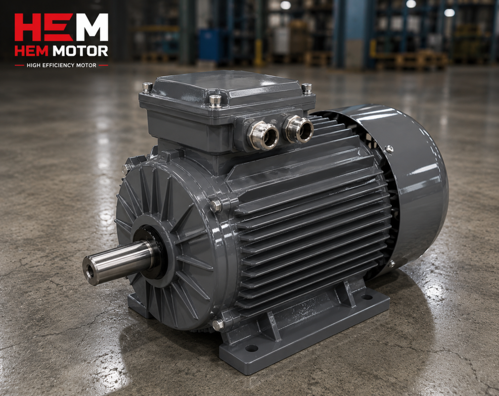
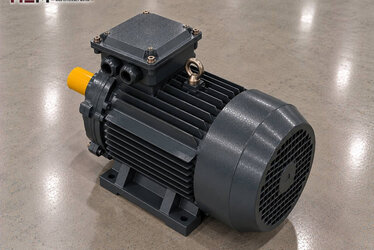
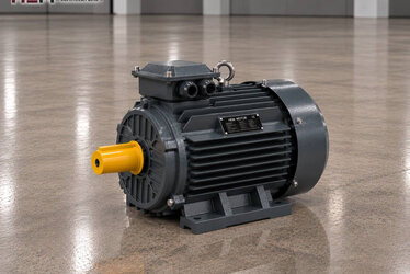
The drive motor of a pump that draws water from a well usually stands at the wellhead, above ground, while the pump itself works far below, under the water level. A long shaft, a gearbox or a direct flange links the two. This page covers the three-phase electric motor that turns such surface-driven well pumps; the overall picture of pump types is gathered on our main Pump Electric Motors page.

Motor above the well, pump below the water level
The idea behind a surface-driven layout is simple: the electric motor stays in a dry, accessible place where it is cooled by air. Nobody has to go down the well for maintenance; the bearings, terminal box and fan of the motor are checked at the wellhead.
The price of this layout is paid on the mechanical side. The longer the shaft between pump and motor, the more alignment, intermediate bearings and shaft loads matter. Choosing the motor is therefore not just a matter of power and speed; how the motor is seated and which loads it must carry also have to be clear.
Vertical turbine pump and V1 vertical motor
In the vertical line-shaft turbine pump, common in farm and drinking-water wells, the bowl assembly hangs near the bottom of the well. The shaft rises inside the discharge column up to the drive head at the surface. The motor sits vertically on top of this head, shaft pointing down.
This arrangement uses the V1 mounting: flanged frame, shaft down. Alongside the horizontal B3/B5/B14/B34/B35 arrangements, our three-phase range includes V1, V3, V5, V6 and V15 vertical versions depending on frame size; we check together at the order stage the flange and shaft dimensions that must match the drive head. More on flanged frames is on the flange-mounted motors page.
On a vertical motor the fan is at the top, so on an open site rain and dust fall onto the upper cover. Sheltering the wellhead with a hut or canopy is good practice so that water does not collect on the motor frame. IP55 protection withstands rain, but the motor is not designed to be submerged.
Axial thrust: does the pump carry it or the motor?
In a line-shaft pump, the water column in the riser and the hydraulic force of the impellers, together with the weight of the shaft, create a downward thrust. Where this load is taken depends on the pump design. Some drive heads have their own thrust bearing and the motor only provides rotation. In other layouts part of the thrust is transferred to the motor bearings.
So check the pump manufacturer's data before ordering the motor: if an axial load must be carried on the motor side, its value and direction are stated in the order and the bearing arrangement is confirmed accordingly. In wells driven through a coupled right-angle gearbox, the gearbox usually takes the thrust and the motor is connected horizontally.
Where the motor goes, by well layout
| Well layout | Motor position and mounting | Watch out for | Order information |
|---|---|---|---|
| Vertical line-shaft turbine pump | Vertical on the drive head, V1 flanged | Axial thrust, shaft alignment, rain on the top cover | V1, flange and shaft size, thrust load on the motor |
| Right-angle gearbox drive | Horizontal, B3 foot-mounted; coupled to gearbox input | Gear ratio, coupling alignment, base rigidity | Speed, shaft size, direction of rotation |
| Surface suction pump on a shallow well | Horizontal B3 or B35, coupled to the pump | Suction lift limit, air in the suction line | Power, speed, mounting type |
| Pressure boosting at the wellhead or after the tank | On a horizontal or vertical in-line pump | Variable demand, inverter with pressure sensor | Voltage, inverter use, cable length |
| Municipal well field (several wells) | Same frame and mounting at every well | Spare motor, common flange size | Quantity, spare needs, existing nameplates on site |
The layouts in the table are guidance; the final decision rests on the pump manufacturer's data and the site conditions of the well. For horizontal pumps see the centrifugal pump motor page, and for in-line pumps the inline pump motor page.
Long running hours in the irrigation season
An irrigation well motor may run day and night through the summer; municipal wells are in service all year. What matters here is less the sudden load than the continuous thermal load. The rated power of the motor must not fall below the power the pump needs at its operating point; otherwise the winding temperature approaches its limit every day.
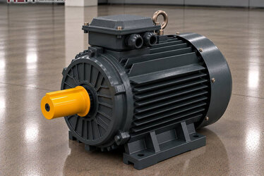
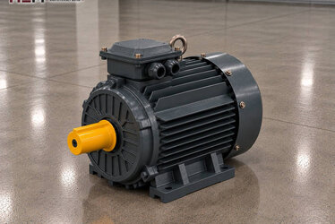
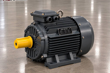
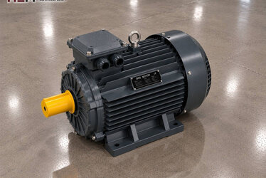
Four-pole examples from a class often seen on well sites: 180L-4, 22 kW (rated 1,470 rpm, 39.7 A at 400 V), 250M-4, 55 kW (rated 1,485 rpm, 97.6 A) and 280M-4, 90 kW (rated 1,486 rpm, 155 A, SF 1.15). These models are for orientation; which one fits is decided by the pump's power demand, the required speed, the connection type and the duty of the well. All three have a cast iron frame, IP55 protection and class F insulation for a 50 Hz supply. A PTC or PT100 sensor to monitor the winding and an anti-condensation heater against moisture during long stops are order options.
Long cables, voltage drop and starting
Wells are often far from the transformer and the main panel. Voltage drops along a long supply line; at lower voltage the motor draws more current to deliver the same power and heats up. The cable cross-section must be calculated by the electrical designer according to line length and motor current. The voltage measured at the motor terminals should be close to the nameplate value.
A direct-on-line start of a large motor pulls the voltage down sharply on a weak rural grid. That is why well panels prefer a star-delta switch, soft starter or drive that limits starting current. Motors labelled 400/690 V run in delta on a 400 V grid and are suitable for star-delta starting.
Feeding the motor from a drive to match well output to demand is possible; our three-phase models are suitable for this. Two points should be discussed up front, though: if the motor will turn at low speed and full load for long hours, its own fan may not be enough and a separate fan is added; if the cable between drive and motor is long, a dv/dt or sine filter is fitted at the output to protect the winding from voltage spikes. Simply state these two conditions in the order. Details: inverter-compatible motors.
Dry running and panel-side protection
The water level in a well drops during the season. If it falls below the pump intake, the pump runs dry; in line-shaft pumps this damages the shaft bearings and impellers. This protection is provided by the panel, not the motor: level electrode or float switch, a relay monitoring current drop, phase sequence and phase loss relay, motor protection circuit breaker.
Reverse rotation is another risk specific to wellheads. When the pump stops, water flowing back down the column can turn the impellers, and with them the motor, backwards. Restarting at that moment causes mechanical stress; that is why a restart delay in the panel and a check valve on the pump matter. Compare the motor's direction of rotation with the arrow on the pump before commissioning.
What to send for a quotation
For a quick and accurate quotation, state the type of pump or machine (line-shaft, right-angle gearbox, surface pump); then add the motor power in kilowatts, the required speed, the site voltage, the mounting (V1, B3, B35…) and how many units you need. The axial load on the motor, flange and shaft size, cable length and starting method also sharpen the selection.
If you are replacing a motor, you can send a photo of its nameplate via the send your motor nameplate page. Current prices are shown on the product pages and in our online shop; for deep well motor prices or a situation specific to your well, get in touch with us.
Frequently Asked Questions
Can I also get a motor for a submersible pump?
Motors that are lowered into the water inside the well are not part of our 2026 catalogue. The motors on this page are for line-shaft or horizontally driven pumps working at the wellhead, on the surface.
How is the axial load on the motor of a line-shaft pump determined?
The value comes from the pump manufacturer's data. If the drive head carries the thrust itself, the motor only provides rotation; if load is transferred to the motor, state its value and direction in the order and the bearing arrangement is confirmed accordingly.
Does motor selection change if the well is far from the transformer?
The motor power stays the same, but cable cross-section and starting method become important. The voltage drop calculation should be made by the electrical designer; if an inverter is used on a long line, the need for a filter should be stated in the order.
Does the motor have any protection against dry running?
Dry running is a pump problem and is solved in the panel: level electrode, underload relay and phase protection. On the motor side, a PTC or PT100 winding sensor can be added as an order option.
Can I find a motor of the same size to replace my existing well motor?
An equivalent model is searched by the power, speed, frame size and mounting type on the nameplate. Send the nameplate photo and the flange size, and we will determine the suitable HEM Motor model together.