English
 Français
 Türkçe
 Español
 Русский

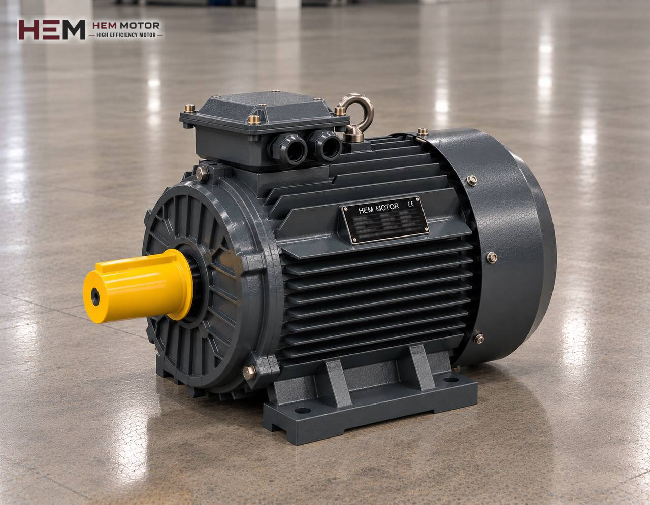
In ceramic tile, sanitaryware and tableware plants, the body sent to forming is first prepared by grinding clay, kaolin, feldspar and quartz together with water for many hours. The drum ball mill that does this job is, from the motor's point of view, one of the most stubborn loads in the plant: a full cylinder has to be set in motion and then held at the same speed for hours. This page deals with the electric motor that turns the mill; for the rest of the line see the brick, tile and ceramic production line motors page.

What Does a Slip Mill Do Inside?
The mill is a horizontal cylinder whose inner surface is covered with a wear-resistant lining. Raw material, water and grinding balls are loaded into it. As the drum turns, the balls are carried up along the wall, fall from a certain height to crush the material and grind it finer by rubbing against each other. The resulting fluid body is called slip; after sieving and resting in tanks it goes to the spray dryer or to the casting department.
Grinding efficiency is very sensitive to drum speed. In a drum turning too slowly the balls only roll; in one turning too fast they stick to the wall by centrifugal effect and do not fall. The correct speed is set by the mill builder according to drum diameter and filling ratio. How steadily the motor holds this speed directly affects batch time and particle fineness.
The Load the Mill Puts on the Motor
Breakaway torque: the first turn is the hardest
In a stopped mill, balls and slip are gathered at the bottom of the drum. During long stops the slip settles and the gaps between the balls tighten. At the first moment the motor has to lift the centre of gravity of this mass to one side; so the torque needed at start rises above the torque in continuous running. The full drum's weight and inertia also lengthen acceleration time.
Continuous, steady running
Once at speed the load is fairly smooth. Batch mills turn throughout a charge, continuous mills run without interruption for days. During this time the motor may work close to its rated power, so winding temperature and bearing lubrication become decisive. Small changes in current usually reflect changes in slip density.
Discharge and positioning
When a batch is finished, the drum must be stopped with the discharge hatch facing down. In some plants the main motor does this at low speed, in others a separate small auxiliary drive is used. If the main motor is to run at low speed for long periods for this purpose, cooling should be discussed from the start.
Gearbox, Belt and Pinion: Drive Arrangements
There is a large gap between motor speed and drum speed; it is closed in several stages. On small and medium mills the motor turns a gearbox via belt and pulley, and the gearbox turns the drum shaft or a gear fixed around the drum. On large mills a pinion on the gearbox output meshes with a girth gear wrapped around the drum. The belt arrangement softens the sudden strain at start somewhat and makes ratio changes easier.
Motors flanged to a gearbox input commonly use a B5 or B35 frame, while belt drives use a foot-mounted B3 frame and a tensioning slide. Frame size determines which mounting is possible; the choice is made among foot, flange, foot-and-flange and shaft-down or shaft-up vertical options, and the flange diameter and shaft end dimension are cross-checked at order. Details of gearbox matching are on the electric motors for gear reducers page.
Starting Method and Speed Adjustment
To set a full drum in motion, the motor must deliver enough torque at start. Because starting torque drops markedly in star-delta connection, the motor may stay stuck in the star stage when starting with a settled charge. That is why mill builders often recommend a soft starter, a frequency inverter or, in belt drives, a stepped acceleration; the decision is made with the machine's data.
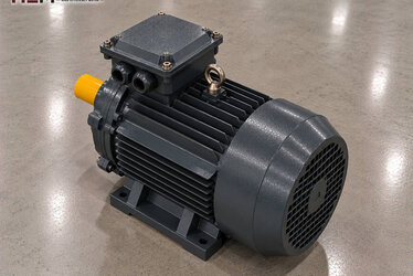
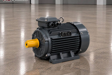
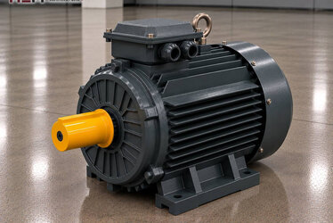
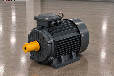
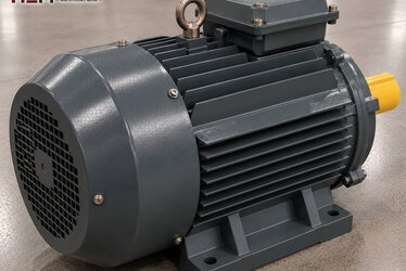
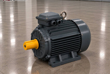
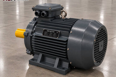
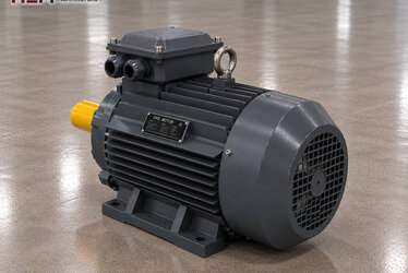
A frequency inverter also makes it possible to adjust drum speed for different recipes. HEM's three-phase motors can be driven by an inverter. However, since the motor is cooled by the fan on its own shaft, a separately powered cooling fan may need to be added if full load is carried while the drum turns slowly; when the cable between drive and motor is long, an output filter is considered to protect the winding. Send these details with your order. More information is on our inverter-compatible electric motors page.
Example HEM Models for Mill Drives
| Mill arrangement | Motor condition | Key selection criterion | Example HEM model |
|---|---|---|---|
| Small batch mill, belt-driven | Heavy start, then smooth load | Pulley ratio, tensioning slide | 11 kW, 970 rpm, 160L-6 cast iron |
| Medium batch mill, geared | Long acceleration, hours of running | Gearbox input, starting method | 30 kW, 980 rpm, 225M-6 cast iron |
| Large mill, pinion and girth gear | High inertia, uninterrupted running | Soft start, winding temperature monitoring | 90 kW, 988 rpm, 315M-6 cast iron |
| Slip tank agitator | Continuous, low speed | Gearbox flange, vertical mounting | 5.5 kW, 1,460 rpm, 132S-4 cast iron |
The listed models are given for guidance; the actual selection is made by considering the full drum weight, the required drum speed, the drive ratio and the operating environment together. The 90 kW model in the table has a service factor of 1.15.
Wet Environment, Ceramic Dust and Maintenance
Two separate hazards coexist in the mill hall. Fine, abrasive dust flies at the loading mouth where dry raw material is tipped; on the discharge side slip splashes and the floor is constantly wet. Our motors are IP55 protected; however, hosing down the motor or spraying water directly onto it is not a situation this protection class covers. If such a practice exists, the motor must be shielded or a special motor selected; state this in your order.
Slip stuck to the cooling fins forms a crust when it dries and makes it harder for the motor to release heat. Regular cleaning, keeping to bearing lubrication intervals and checking belt tension are the habits that determine a mill motor's life. For mills stopped for long periods, an anti-condensation heater for the winding and a PTC/PT100 sensor for monitoring winding temperature can be added as order options. For this heavy, continuous drive the cast iron frame series is the natural choice.
When Requesting a Quote for a Mill Motor
To clarify your needs, share the following: the machine (batch or continuous mill, tank agitator), required power, motor speed, site voltage, mounting type (foot, flange, attached to gearbox) and quantity. If you send a photo of the existing motor's nameplate, equivalent matching is faster.
You can see all models on the buy electric motors page; the current price is shown on each product page. Our WhatsApp and phone details are on the contact page.
Frequently Asked Questions
Why is the mill hard to start after a long stop?
While standing, the slip settles and fills the gaps between the balls; the charge behaves like a solid mass at the bottom of the drum. On the first turn the motor spends more torque than normal to lift this mass to one side. Turning the drum briefly at intervals to loosen the charge before starting, or a suitable starting method, eases the problem.
Can I increase drum speed by changing the motor?
A motor with a different number of poles changes drum speed in the same proportion through the drive ratio, and in a drum approaching critical speed the balls may stop falling. If speed adjustment is needed, an inverter or a pulley change within the range recommended by the mill builder is the better route.
Why does the mill motor's current change during a batch?
As grinding progresses, slip density and viscosity change, and the way the balls fall changes accordingly. A slow change in current is normal; sudden jumps may signal a bearing, gear or belt problem.
Is the same motor chosen for the tank agitator?
No, the agitator's load is lighter but uninterrupted, and the motor is usually mounted vertically on a gearbox. Power, mounting type and gearbox flange are assessed separately.