English
 Français
 Türkçe
 Español
 Русский

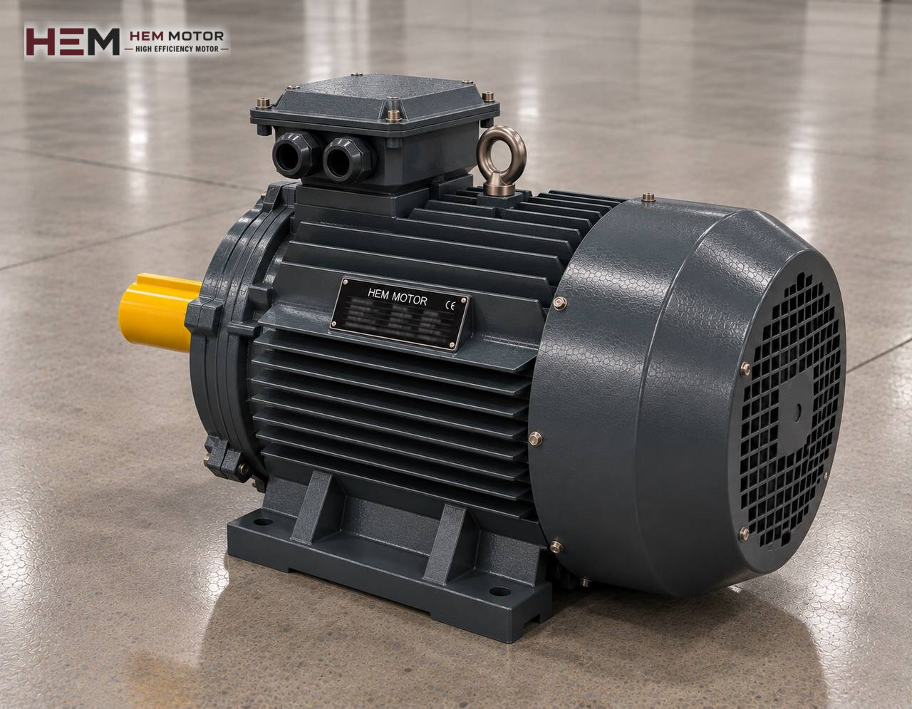
In the production of ceramic tiles, porcelain stoneware and refractory bricks, shape is given not with moist clay but with granulated powder from the spray dryer. The powder is filled into the die cavity and compacted under very high pressure into a green tile. What the electric motor does on the press that produces this pressure changes completely with the type of press. All drives of the line are on the brick, tile and ceramic production line motors page; here only dry powder forming presses are covered.

How Does Dry Powder Pressing Work?
A pressing cycle lasts a few seconds. The feed carriage moves over the die, drops granules into the cavities through its grid and withdraws. The upper punch comes down, first makes a low-pressure pre-press and lets the air in the powder escape. Then the main pressing follows; the punch dwells for a set time, rises, and the lower punch pushes the tile up out of the die. With the next feed movement the tile is pushed forward onto the belt leading to the dryer.
During the cycle the force rises from zero to its peak and falls again within very short times. The system driving the press must therefore either store this force quickly and release it, or supply enough pressurised oil exactly when needed. The two approaches give rise to two different press families.
The Motor's Job on a Hydraulic Tile Press
Today most tile production is done on hydraulic presses. On these machines a large-bore cylinder moves the punch; the electric motor's job is to turn the pump set. The oil delivered by the pump charges hydraulic accumulators, and at the moment of pressing the oil released from the accumulators drives the cylinder quickly. So the motor covers not the peak power of the stroke but the average energy used over the cycle.
Motor power is linked to pump flow, system pressure and strokes per minute. On large presses several pumps and motors may be connected to the same hydraulic unit. For the calculation method see the hydraulic pump electric motors page; the values given by the press builder always take priority. Besides the main pump, the oil cooling and filtration circuit pump, the cooler fan and the lubrication pump also run on separate small motors.
Motor turning continuously, load varying
On a hydraulic press the main motor does not stop during the shift. While the accumulator charges the pump is loaded; once charged it is unloaded and the motor runs at light load. This fluctuation appears as a regular swing on the ammeter. As oil temperature rises, leakage losses increase and the motor stays loaded longer for the same work; maintaining the oil cooling circuit protects the motor too.
Mechanical Friction Screw Press
Friction screw presses are still used for refractory bricks and some special parts. On this press the motor continuously turns two friction discs on a horizontal shaft. When one disc is pressed against the large flywheel, the flywheel turns and drives the big screw down, and the ram strikes the die; when the other disc makes contact, the ram returns upward. The pressing energy comes from the rotational energy stored in the flywheel.
In this design the motor load is pulsating: after each blow the discs and flywheel lose speed and the motor restores it. When the disc is belt-driven, the motor sits on a tensioning slide with a foot-mounted frame. Because of the heavy disc and pulley assembly, run-up is long; remember that starting torque drops in star-delta connection, and choose the starting method together with the machine builder.
Other Movements Around the Press
The feed carriage moves back and forth with its grid; on older presses a geared motor and crank make this movement, newer ones use a hydraulic or servo axis. The belt and elevator carrying powder from the granule silo to the feed hopper, the tile turnover and brushing unit at the press outlet and the dust extraction fan for die cleaning run on separate motors. Most of these auxiliary drives are small and run continuously; for belts and elevators the electric motors for gear reducers page helps with selection.
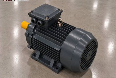
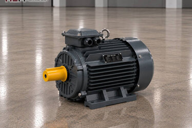
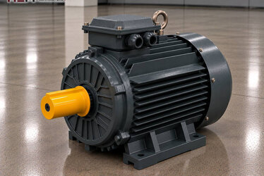
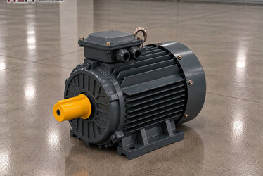
Example HEM Models for a Ceramic Press
| Drive | Load seen by the motor | First data to check | Example HEM model |
|---|---|---|---|
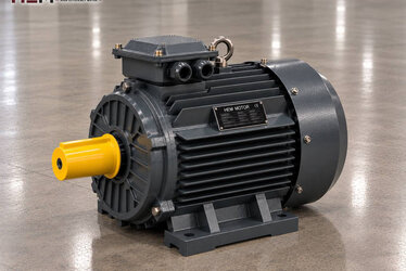
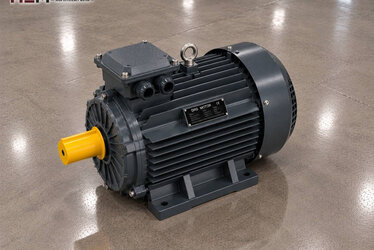
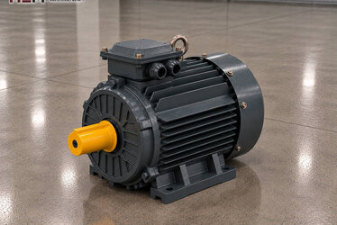
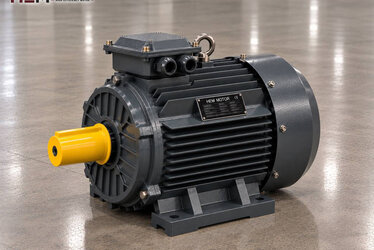
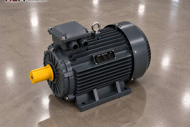
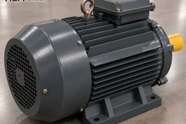
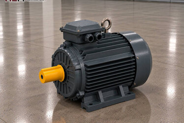
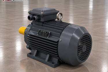
| Hydraulic press main pump (mid-size press) | Continuous rotation, varies with accumulator charging | Pump flow, pressure, strokes per minute | 37 kW, 1,485 rpm, 225S-4 cast iron |
| Hydraulic press main pump (large press) | Continuous rotation, high average power | Number of pumps, unit design | 75 kW, 1,486 rpm, 280S-4 cast iron |
| Friction screw press disc drive | Pulsating, heavy start | Pulley ratio, flywheel inertia | 15 kW, 1,465 rpm, 160L-4 cast iron |
| Oil cooling and filter pump | Continuous, light | Circuit flow, flange connection | 2.2 kW, 1,450 rpm, 100L1-4 aluminium |
The models are given as examples; the right motor is determined by examining the press's real load, required speed, connection type and operating environment together. The 75 kW model has a service factor of 1.15.
The Motor Against Granule Dust, Oil and Heat
The air in the press hall carries very fine, abrasive ceramic dust. This dust builds up on the motor's cooling fins and fan cover and, combined with the oil mist around the hydraulic unit, forms a sticky layer. Our motors come with IP55 protection and class F insulation; with regular cleaning they suit this environment. Washing the frame with compressed air or water, however, is not something this protection class is designed for; if such a practice exists, a shield or a special motor is needed, so state it in your order.
Hydraulic unit motors are mostly connected to the pump with a bell housing and coupling, so flange B5 or foot-and-flange B35 frames are common. On some units the motor stands vertically on top of the tank. Depending on frame size, B3, B5, B14, B34, B35 and vertical V1, V3, V5, V6, V15 options are available; we confirm flange and shaft dimensions together at order. For main pump motors running continuously for long periods, a PTC/PT100 sensor fitted in the winding and an anti-condensation heater are order options. For main motors the cast iron frame range is the natural choice.
What Should You Send Us for a Press Motor?
In your request state the machine type (hydraulic tile press, friction screw press, feed or oil cooling drive), the required power and speed, the site voltage, the mounting arrangement and the quantity. If you send the nameplate photo of the existing motor together with the pump nameplate, matching takes much less time.
All models are listed in the electric motor shop; the current price is on the product page. For WhatsApp and phone, use our contact page.
Frequently Asked Questions
Why is the motor of a hydraulic tile press loaded between strokes rather than during pressing?
Most of the oil needed for pressing comes from the accumulators. The motor and pump recharge the accumulators between two strokes. That is why current rises during charging, not at the exact moment of pressing.
Does fitting a more powerful main pump motor increase the pressing force?
No. Pressing force is set by system pressure and cylinder bore. A more powerful motor only lets the pump carry more load; without changing the pump and settings, the force does not increase.
Why does the screw press motor have to be replaced so often?
The motor turning the friction discs continuously takes a shock at every blow; belt tension, disc wear and frequent starts together strain the bearings and winding. Belt and disc maintenance, a suitable starting method and the right pulley ratio extend its life.
Which frame suits motors in the press hall better?
Cast iron frames stand out on main drives carrying vibration and continuous load. On small, lightly loaded drives such as the oil cooling pump, aluminium frames can also be used; the decision depends on mounting location and flange size.