English
 Français
 Türkçe
 Español
 Русский




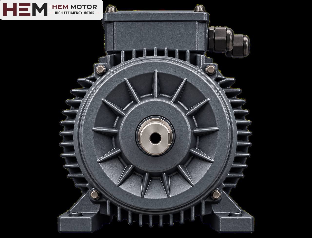

A scroll fan is a radial (centrifugal) fan named after the spiral shape of its housing. It draws air in along the axis, throws it outwards and converts it into pressure thanks to the spiral casing. It is widely used in ventilation, extraction, drying, combustion air and process lines. When buying an electric motor for these fans, power and speed are of course the first questions; but the type of connection, direction of rotation, mounting position and the environment in which the fan operates are just as decisive. This article lists what to check before ordering a scroll fan motor, in the form of a buyer's checklist.
Get to know the fan first: where is the motor on the fan?
Scroll fans are combined with the motor in three basic arrangements. Without knowing which arrangement you have, it is not possible to choose the right motor.
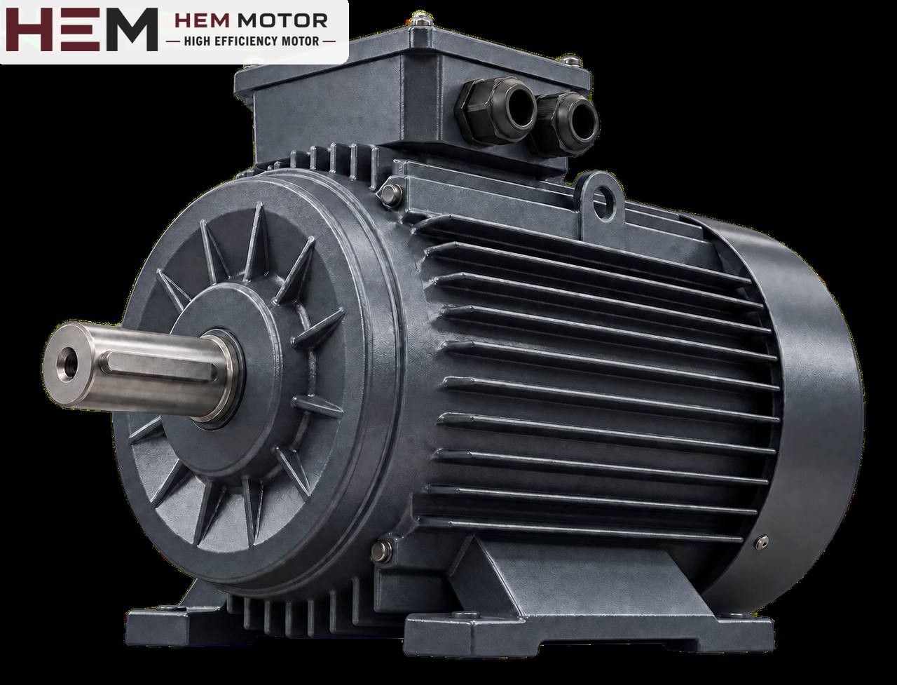
- Direct-coupled (impeller on the motor shaft): The impeller hub is fitted directly onto the motor shaft. This is common on small and medium-sized fans. The motor carries the weight and unbalance of the impeller directly in its own bearings. The motor is usually held by a flange fixed to a bracket or to the casing.
- Coupled: The fan has its own shaft in bearings; the motor sits on a base by its feet and is connected by a flexible coupling. The impeller load stays in the fan bearings.
- Belt and pulley: The motor is usually placed on a slide rail beside or below the fan casing. Fan speed comes from the motor speed and the pulley ratio; this provides adjustment flexibility but places a side load on the shaft.
For a motor bought for a direct-coupled fan, the shaft end, flange and bearing load become critical. On coupled and belt-driven fans, the foot connection and the shaft end dimension come to the fore.
Speed: why is the number of poles not changed on a scroll fan?
The pressure and flow a scroll fan produces are determined by the impeller diameter and the speed. The fan manufacturer designs the impeller for a certain speed; this is usually the speed of a 2-pole (3,000 rpm synchronous) or 4-pole (1,500 rpm synchronous) motor. The value read on the nameplate is the rated speed: for example 2,895 or 2,905 rpm on a 2-pole motor, and 1,450 or 1,460 rpm on a 4-pole motor.
On a direct-coupled fan, changing the number of poles changes the entire characteristic of the fan. If the speed halves, the pressure falls to a quarter; if the speed doubles, the fan power rises to around eight times and the impeller may exceed its strength limit. For this reason, keeping the number of poles shown on the nameplate is the basic rule when ordering a replacement motor. If the speed needs to be changed, this is done with the fan manufacturer's approval and usually through the pulley ratio or a frequency inverter.
Speed adjustment with a frequency inverter
Our three-phase series are suitable for speed control with a frequency inverter; for long periods of full-torque operation at low speed an external fan may be required, and if the cable between drive and motor is long a dv/dt or sine filter is considered; these conditions are stated with the order. Since torque on a fan load decreases as speed falls, the risk of overheating at low speed is generally limited; however, if operation above 50 Hz is planned, the suitability of the motor and the impeller must be assessed separately. Details are on the inverter operation page.
Direction of rotation and casing position
On scroll fans, the direction of rotation of the impeller must match the opening direction of the spiral casing. A radial fan rotating in reverse still moves some air; this is why the error may not be noticed at first glance. However, flow and pressure drop noticeably, the current differs from what is expected and the system runs inefficiently.
- Look at the direction-of-rotation arrow on the fan casing; if there is no arrow, determine the direction from the opening direction of the casing.
- On three-phase motors, the direction of rotation is reversed by swapping two phases. Before the motor is connected to the impeller, the direction is checked with a short run.
- The cooling fan of standard motors is usually designed to work in both directions. Even so, stating the required direction of rotation in the order allows a possible unidirectional cooling arrangement, especially at higher powers, to be discussed in advance.
The casing position (outlet facing up, sideways or down) does not directly change the motor selection, but it affects the position of the motor and access to the terminal box. Which side the terminal box should be on should be considered in advance so that cable entry can be made easily.
Mounting arrangement: foot-mounted, flange, vertical
The most common arrangements on scroll fans are B3 (foot-mounted), B5 or B14 (flange) and B35 (foot and flange). On roof-mounted or vertical-axis fans the motor may run in a vertical position (V1 shaft down, V3 shaft up). In vertical operation the bearings also carry the weight of the impeller in the axial direction; for this reason the mounting position must be clearly stated in the order.
B3, B5, B14, B34, B35 and vertical V1/V3/V5/V6/V15 arrangements are offered according to the frame; the flange size is confirmed with the order. A flange being called "B5" does not mean it matches the bolt circle on your fan bracket. For dimensions, see the technical drawings; the arrangements available are summarised in the question on mounting arrangements.