English
 Français
 Türkçe
 Español
 Русский

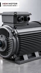
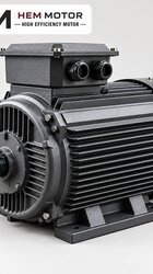
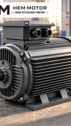
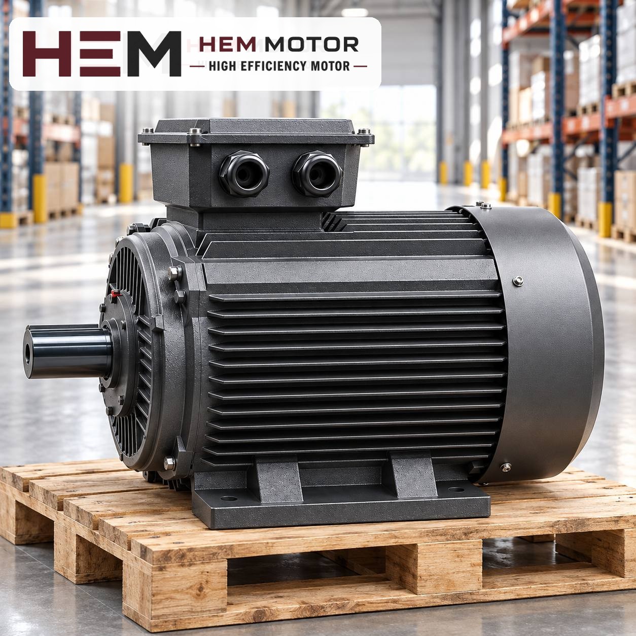

On a plastic injection moulding machine, the hydraulic pump motor is not selected from the clamping force or the machine tonnage, but from the pump displacement, the system pressure and the way the load is distributed over one moulding cycle. In every cycle the pump sees a peak load lasting a few seconds and then runs at low load for a long time. The right motor is one that can carry this peak while its average heating over the cycle stays within limits.
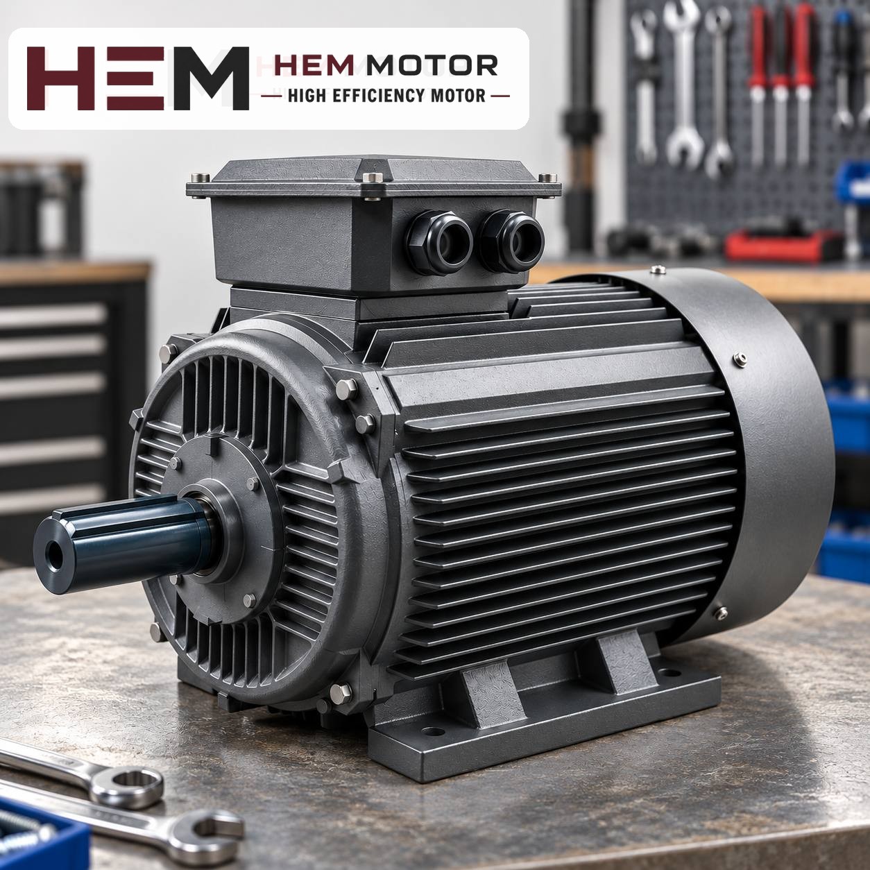
What does the pump motor go through in one moulding cycle?
On a conventional hydraulic injection moulding machine the motor runs continuously as long as the machine is on; it is the valves, not the pump, that start and stop. Each step of the cycle asks the pump for a different flow and pressure, and the power the motor delivers to the shaft fluctuates accordingly.
- Mould closing and locking: high flow for fast movement, a short burst of high pressure at the moment of locking.
- Injection: the step where flow and pressure both reach their highest at the same time; this is usually where the motor sees its largest load.
- Holding pressure: pressure stays high while flow drops sharply; the power demand falls noticeably.
- Plasticising (dosing): the hydraulic motor turning the screw needs flow at medium pressure for a long period.
- Cooling, mould opening and ejection: the pump is mostly unloaded; the motor runs almost without load.
This picture leads to two conclusions. First, the rated power of the motor does not have to equal the peak power; second, the larger the gap between peak load and average load, the more carefully the selection has to be calculated.
The motor load depends on the pump type
Two machines of the same tonnage may need different motors depending on the pump arrangement they use. Before replacing the motor, find out which pump is running on the machine.
Fixed displacement pump with proportional valve
A fixed displacement gear or vane pump always delivers the same flow for a given motor speed. Excess oil returns to the tank through the proportional valve or the unloading circuit. In this arrangement the motor works with a certain base load even in steps where there is no work, and the oil heats up more.
Variable displacement (pressure-compensated) pump
A variable displacement piston pump delivers only as much oil as is needed. During cooling and waiting steps the motor load falls noticeably; the peak load still occurs at the moment of injection.
Servo-pump systems
On some newer machines the pump is driven by a servo motor and a dedicated drive; speed changes at every step and the motor may stop while waiting. This duty requires a special motor; it may fall outside the scope of the standard series in HEM Motor's 2026 catalogue, so ask us with the nameplate and application details. For variable speed pump arrangements built with an induction motor and a frequency inverter, the general conditions on our inverter operation page apply.
Calculating the power: peak value and cycle average
The basic relationship for hydraulic power is simple: power (kW) = pressure (bar) × flow (l/min) / 600. Taking the overall pump efficiency into account gives the power required at the motor shaft. Flow, in turn, is the pump displacement per revolution multiplied by the rated speed of the motor.
The figures below are a hypothetical example and do not belong to any specific machine. A pump with a displacement of 40 cm³/rev, driven by a 4-pole motor running at 1,465 rpm, delivers about 58.6 l/min. If 140 bar is required during injection, the hydraulic power is 58.6 × 140 / 600 ≈ 13.7 kW; with an overall efficiency of 0.85, about 16 kW is needed at the motor shaft.
These 16 kW appear in only a few seconds of the cycle. When a time-weighted average (root mean square, RMS) is taken together with the low loads of the other steps, the value in this hypothetical cycle drops to the 9–10 kW range. In that case the machine builder may have chosen an 11 kW motor; because the peak rises to about 1.5 times the rated power, the torque values of the motor should be checked separately against the technical catalogue or confirmed with us.
| Value to check | Where to read it | Effect on motor selection |
|---|---|---|
| Pump displacement (cm³/rev) | Pump nameplate or machine manual | Determines flow together with speed |
| Maximum system pressure | Relief valve setting, hydraulic diagram | Determines peak power |
| Cycle time and step durations | Machine control screen | Determines average heating |
| Existing motor power and speed | Motor nameplate | Main reference for a replacement |
Why a larger motor is usually not the answer
Fitting a larger motor because the injection speed is not sufficient does not increase the flow. Flow comes from pump displacement and speed; a more powerful motor at the same 4-pole speed turns the pump at the same rate. Raising the speed means changing the pump itself or the hydraulic circuit, which is the machine builder's domain.
Raising the speed to 3,000 rpm is not practical either: the maximum permitted speed of many injection pumps is not suited to it, and there is a risk of cavitation on the suction side. For this reason the pole count of the existing motor is kept during a replacement. If the motor keeps tripping the thermal relay, first check whether the pressure setting has been raised, whether the cycle time has been shortened, and what the oil temperature is.
If the power and speed of your existing motor are known, review suitable HEM Motor models and current prices; for an overview of hydraulic applications you can also visit the hydraulic pump motors page.