A hydraulic power unit consists of a tank, a pump, the electric motor that drives the pump and a valve block. The point that causes the most trouble in a unit is often not the motor itself but the place where the motor and pump meet: the bell housing, the coupling, the shaft end and the direction of rotation. If the dimensions of this joint do not match when the motor is replaced, the pump axis runs out of line, the coupling breaks up quickly and the pump seal starts to leak. In this article we explain the steps for checking the motor–pump connection on a hydraulic unit and where the motor power should be read from.
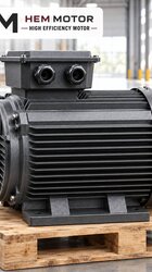
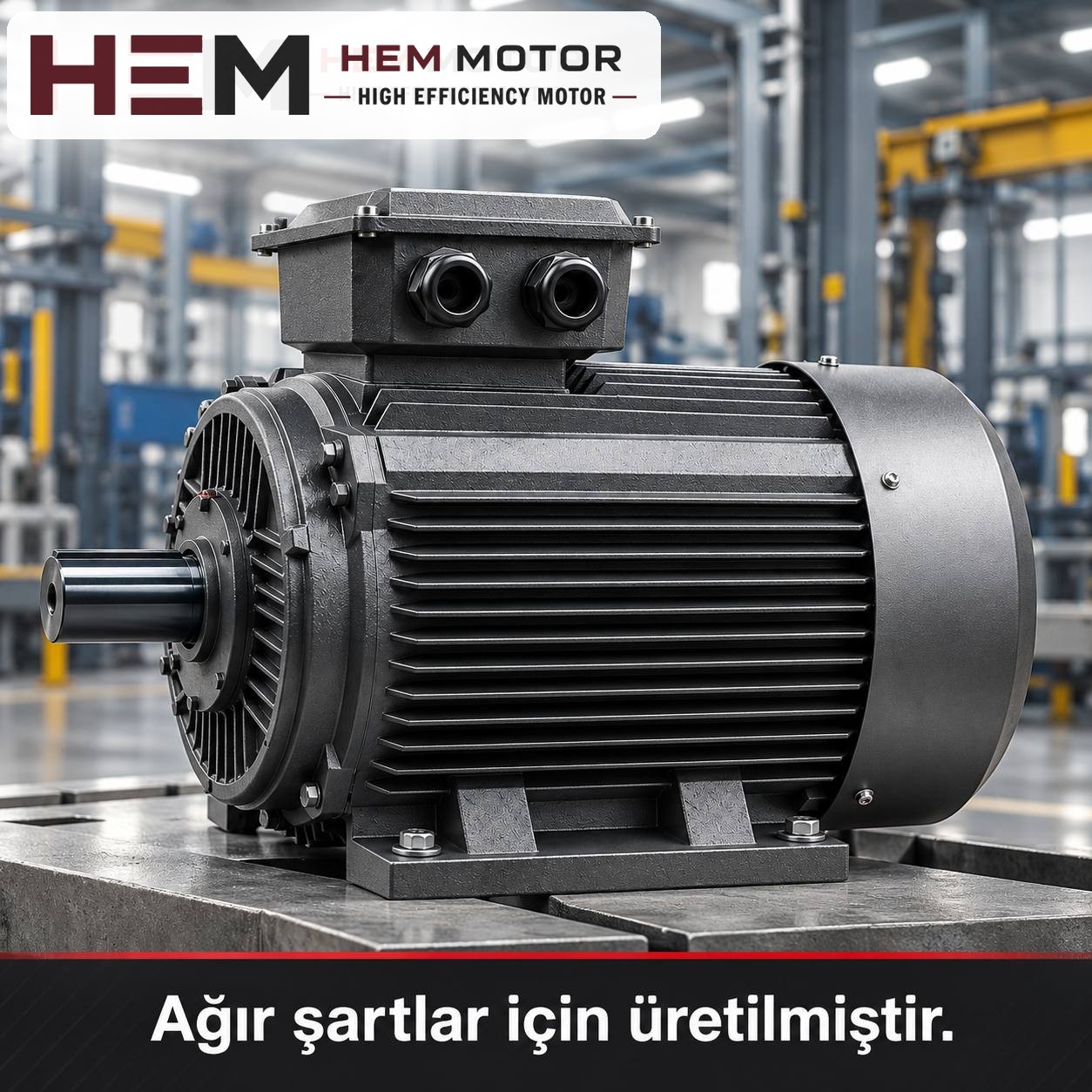
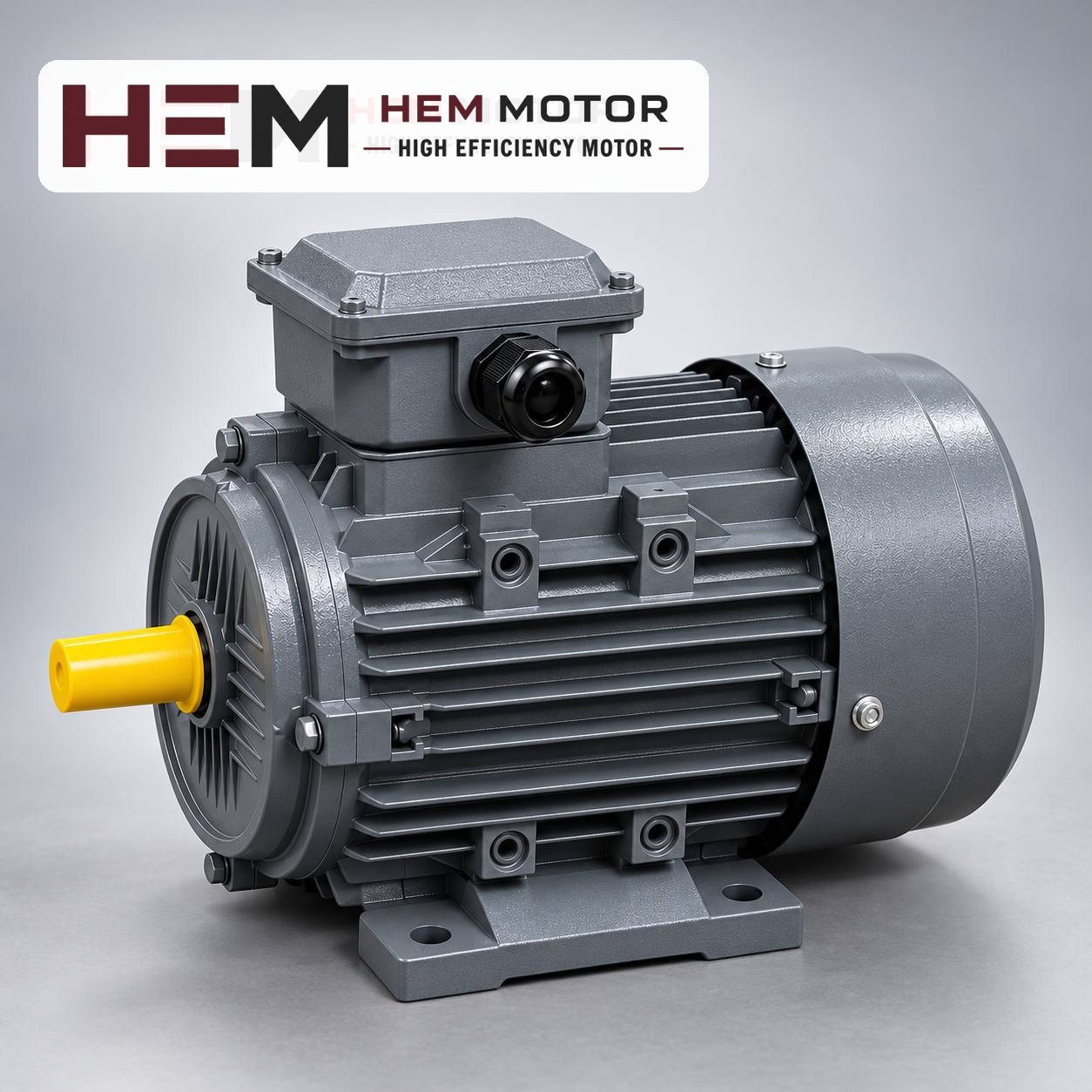
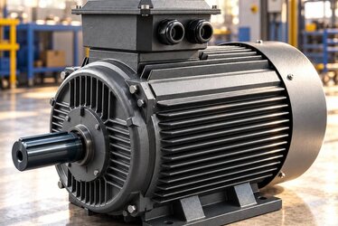
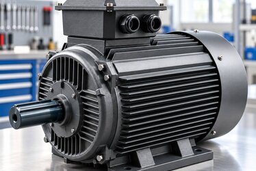
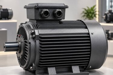
On a hydraulic unit, the motor's shaft end and flange are the reference for the pump connection (representative image).
How are the motor and pump joined?
The most common arrangement on hydraulic units is a bell housing (pump mounting bracket) bolted to the motor flange, with a flexible coupling inside the bell joining the motor shaft and the pump shaft. The pump is attached to the other end of the bell by its own flange. In this way the motor and pump are joined on a single axis without any additional alignment. In this arrangement the motor's mounting is usually one of the following:
B35 (foot and flange): The motor is fixed by its feet to the tank lid or a frame, and the bell and pump hang on the flange. Common on horizontal units; the feet take the weight of the bell and pump off the flange and spread it over the housing.
B5 (flange only): The motor is attached to the bell by its flange alone, without feet. Used when the bell is fixed to a bracket or the tank.
Vertical V1 (shaft down): The motor stands upright on top of the tank lid and the pump hangs into the oil with the bell. Preferred on compact units.
At HEM Motor, B3, B5, B14, B34, B35 and vertical V1/V3/V5/V6/V15 arrangements are offered according to the frame; the flange size is confirmed with the order. Mounting arrangements are not listed per model on the website; the options are summarised on the mounting arrangements page.
Matching the bell housing to the motor
A bell housing is made to two separate sets of dimensions: the motor side and the pump side. On the motor side, the flange spigot diameter, bolt hole circle and number of holes must be the same as on the new motor. If the bell is to be kept, the new motor's flange must be an exact match for the old one; otherwise a new bell is needed.
A common mistake here is to order based only on the words "B5 flange". Even on the same IEC frame, the flange may be offered in different sizes; so the name B5 or B14 on its own does not prove compatibility. Before the replacement, measure and note the following:
The IEC frame size of the old motor (from the nameplate) and the flange spigot diameter
The flange bolt hole circle and number of holes
Shaft diameter, shaft length and key size
The depth of the recess on the motor side of the bell; if the shaft length differs, the coupling halves may not reach the correct position
The flexible coupling inside the bell tolerates small misalignments, but it does not correct poor alignment. The gap specified by the manufacturer must be left between the coupling halves, and both halves must sit fully on the shaft. If the motor shaft butts against the pump shaft, it puts an axial load on the pump bearing and soon leads to failure.
Direction of rotation is a critical issue with hydraulic pumps. Most gear and vane pumps are designed to turn in one direction only and carry an arrow on their housing. After connecting the new motor, check the direction with only a short momentary start; if the direction is wrong, swapping two phases is enough. A pump that runs in the wrong direction for a long time cannot draw oil on the suction side and is damaged by running dry.
Prices and technical data are on the product pages; choose a model and order online.
Motor power is read from the pump and the pressure
The motor power required on a hydraulic unit depends on the flow delivered by the pump, the highest pressure the system works at and the effect of the pump's own efficiency. These values are read together from the pump manufacturer's table or from the unit design. Determining the power by looking at the name of the machine the unit serves is not correct; the same type of press can require a completely different power with a different cylinder bore and speed.
Hydraulic load is often intermittent. In a press cycle the motor works at high pressure for a short time and the pump idles for the rest. So when choosing the motor, one looks not only at the power at peak pressure but also at the average heating over the cycle. If the high-pressure phase lasts a long time, the motor must be chosen so that it can deliver the power of that phase continuously.
Speed: Most hydraulic pumps are selected to run with a 4-pole motor, i.e. at about 1,500 rpm synchronous speed. Do not exceed the highest speed the pump allows; getting more flow from a 2-pole motor can strain the pump's suction limit.
Starting: The unit should not start under pressure. An unloading valve or an idle start circuit prevents the motor from starting under load and makes star-delta starting possible.
Speed control: Our three-phase series are suitable for speed control with a frequency inverter; for long periods at low speed with full torque an external fan may be needed, and if the cable between drive and motor is long a dv/dt or sine filter is considered; these conditions are stated with the order. Details are in the question on use with an inverter.
Example models and where they fit
The models below are taken from the 4-pole series; all have IP55 protection, class F insulation and 50 Hz. The pump flow and working pressure decide which one is suitable.
100L2-4 aluminium frame: 3 kW, 1,450 rpm, IEC 100L, 230/400 V (Δ/Y). The power class seen on small clamping and bench units; connected in star on a 400 V supply.
132M-4 aluminium frame: 7.5 kW, 1,460 rpm, IEC 132M, 400/690 V (Δ/Y). Offers the advantage of a light housing on vertical or horizontal tank-top units.
160L-4 cast iron frame: 15 kW, 1,465 rpm, IEC 160L, 400/690 V (Δ/Y), rated torque 97.8 Nm. When a rigid housing is preferred on press and injection moulding machine units.
180L-4 cast iron frame: 22 kW, 1,470 rpm, IEC 180L, 400/690 V (Δ/Y), rated current 39.7 A. On high-flow press units.
For general information on hydraulic applications, see the hydraulic pump motors page. Current prices are on the product pages.
Hypothetical example: renewing the motor on a 7.5 kW tank-top unit
This section is a hypothetical example for explanation. Suppose that on the tank-top unit of a press brake a 7.5 kW, 4-pole motor in a 132M frame drives a gear pump through a B5 flange and a bell housing.
Since the power, poles and frame remain the same, the 132M-4 is the candidate model; the flange size is confirmed with the order using the spigot diameter and hole circle taken from the old motor.
If the bell and coupling are to be reused, the shaft diameter and key size are checked; the motor coupling half is fitted in the same position.
If the motor is in an area with heavy oil vapour, it is confirmed that the fan cover can draw air.
At first start-up the direction of rotation is checked against the pump arrow; then the pressure is raised in stages, the current is measured and compared with the nameplate value.
Information to send with your order
A photo of the old motor's nameplate and the flange dimensions (spigot diameter, hole circle, number of holes)
Pump type, flow and highest working pressure
Mounting arrangement: B35, B5 or vertical V1
Supply voltage, starting method and drive details if any
The environment the unit is in and its duty cycle
Review suitable models and current prices on the buy electric motors page. To ask about the right model using your existing motor's nameplate, use the send nameplate page, and for other questions, the contact page.
HEM Motor Models Related to This Article
The cards show example models related to the topic. A suitable motor is not chosen by power alone: compare speed, voltage, mounting, shaft and connection dimensions on the product page; if unsure, send a photo of the existing motor’s nameplate on WhatsApp.
On a textile winding machine, what determines the motor choice is how the load changes as the roll grows. If fabric is wound at constant speed and constant tension, when the roll d... More Details
When choosing the turntable motor of a pallet stretch wrapper, the real compatibility is between the motor and the gearbox: the motor speed and the gearbox ratio determine the tabl... More Details
On a diamond wire saw, the main motor sets the cutting speed of the wire by turning the drive wheel. That is why three questions are answered together when choosing the motor: how ... More Details
When replacing the motor on a pillar drill, the easiest route is to choose a motor with the same power, the same number of poles and the same shaft diameter as the old one and to m... More Details
The main motor of a universal lathe is chosen to match the power and speed on the lathe's nameplate, preferably with the same number of poles and the same mounting arrangement. All... More Details
When you replace the motor on a metal band saw, the way to keep the blade speed unchanged is to choose the new motor with the same number of poles (usually 4 poles, the 1,500 rpm c... More Details
We use necessary and optional cookies to improve your experience, enhance content and analyse traffic. Under the GDPR, optional (analytics/marketing) cookies are only used with your explicit consent. Please choose your preference below.
Cookie Policy
 English
 Français
 Türkçe
 Español
 Русский