English
 Français
 Türkçe
 Español
 Русский

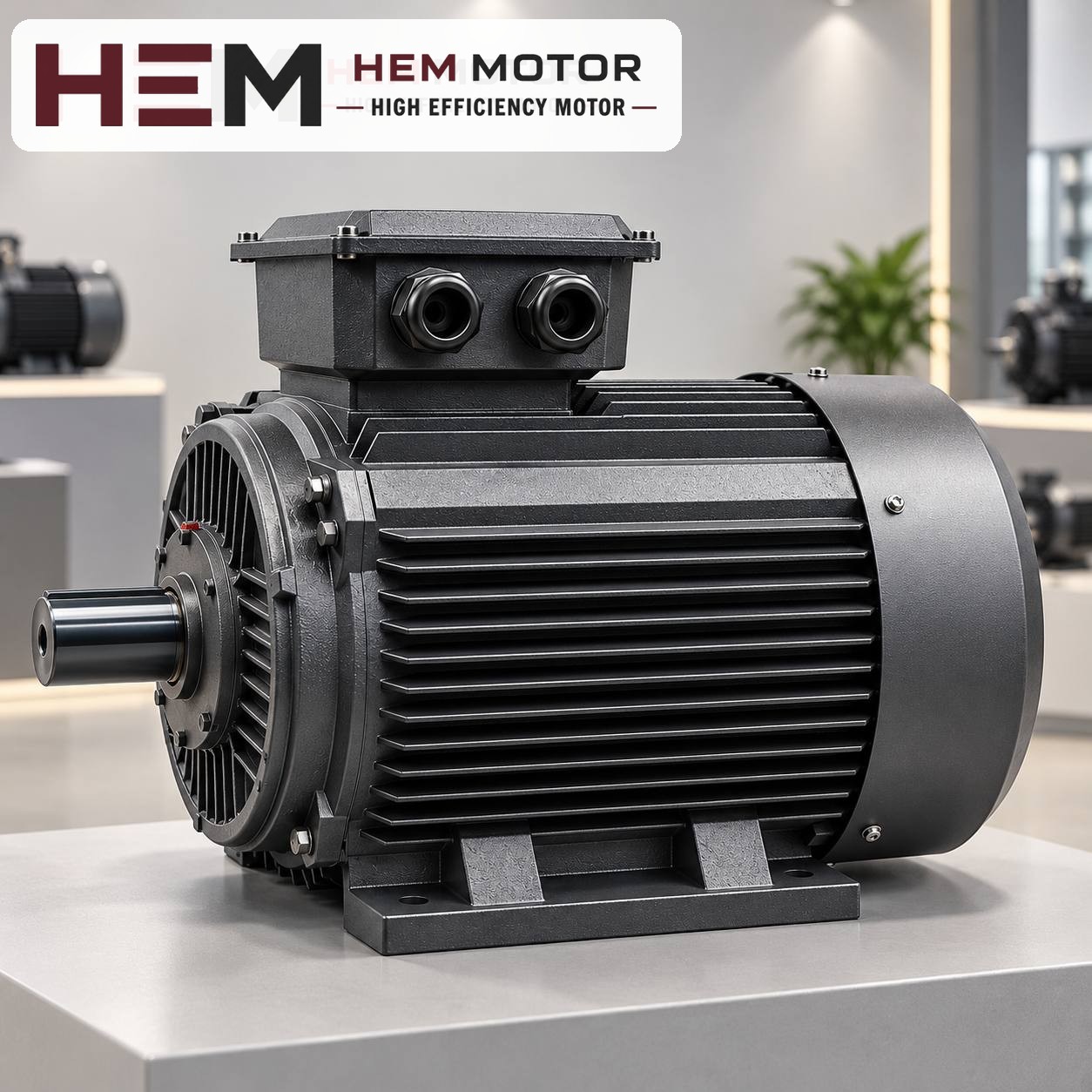

When you replace the motor on a metal band saw, the way to keep the blade speed unchanged is to choose the new motor with the same number of poles (usually 4 poles, the 1,500 rpm class) and leave the gearbox and drive wheel untouched. Blade speed is the combined result of motor speed, gearbox ratio and wheel diameter; if any one of them changes, the cutting speed changes too. This article walks step by step through a motor replacement on a typical metal band saw with a worm gearbox, the speed calculation and the gearbox connection.

How does power reach the blade on a metal band saw?
Unlike a wood band saw, a band saw cutting metal runs its blade much more slowly. That is why there is almost always a high-ratio gearbox between the motor and the drive wheel. The common arrangement is as follows:
- Motor: A three-phase induction motor, usually bolted directly to the gearbox input flange; on some machines a stepped pulley and belt sit in between.
- Gearbox: Usually a worm and wheel type; it reduces speed and increases torque.
- Drive wheel: The large wheel on the gearbox output shaft pulls the blade. The idler wheel on the opposite side tensions the blade.
- Auxiliary drives: The hydraulic unit that lowers the saw arm, the coolant pump and any material feed system run on separate motors.
The replacement usually concerns the main blade motor. Auxiliary motors are assessed one by one; for example, on most machines the coolant pump comes as a small unit integrated with the pump and may fall outside the scope of the standard series.
Blade speed calculation: motor, gearbox, wheel
Blade speed is the circumference of the drive wheel multiplied by the wheel speed. Wheel speed is found by dividing the motor's rated speed by the gearbox ratio. In short: blade speed (m/min) = π × wheel diameter (m) × motor rated speed ÷ gearbox ratio.
A hypothetical calculation
The values below are hypothetical and chosen only to show the method. Assume the machine has a 1.5 kW, 4-pole motor (rated speed 1,445 rpm), a 1:20 gearbox and a 350 mm drive wheel.
- Wheel speed: 1,445 ÷ 20 ≈ 72.3 rpm
- Blade speed: 3.14 × 0.35 × 72.3 ≈ 79 m/min
If a 2-pole motor (about 2,895 rpm) is fitted to the same machine by mistake, the blade speed rises to about 159 m/min, in other words it doubles. In metal cutting this means teeth dulling quickly, the blade overheating and poor cut quality. A 6-pole motor, on the other hand, cuts the speed by about one third and lengthens the cutting time. In short, the number of poles is part of the blade speed the machine was designed for.
Small differences in rated speed (e.g. 1,445 instead of 1,400 rpm) change the blade speed by only a few percent and cause no practical problem. The difference comes from the slip of the induction motor.
What to check on the gearbox connection
If the motor is flange-mounted to the gearbox, the critical point of the replacement is not power but connection compatibility. The input of a worm gearbox is usually prepared for an IEC frame size; the motor shaft goes into the gearbox input bore and the motor flange sits on the gearbox flange.
- Frame code: Compare the IEC frame code on the old motor's nameplate (e.g. 90S, 90L, 100L) with that of the new model. Shaft diameter and flange size depend on this code.
- Flange type: Large flange (B5) or small flange (B14)? Do not rely on the name alone; measure the bolt circle and the spigot diameter. The flange size is confirmed with the order.
- Shaft end and key: The keyway in the gearbox input bore must match the one on the motor shaft.
- Belt-driven arrangement: If the motor sits on a base and drives through a belt, check the foot hole spacing, shaft height and pulley hub.
To compare dimensions, see the 2D technical drawings by frame size. General information on choosing motors for geared drives is also available on the electric motors for gearboxes page.
Speed adjustment: stepped pulley, two-speed motor and drive
Different materials (structural steel, stainless steel, aluminium profiles) need different blade speeds. Machines meet this need in one of three ways, and the motor choice changes accordingly:
- Stepped pulley: There are pulleys of several diameters between the motor and the gearbox; the belt is moved from step to step. A standard single-speed motor is suitable.
- Two-speed motor: A motor whose nameplate shows two powers and two speeds (e.g. 4/2 poles). The winding and connection of these motors are different; they cannot be replaced one-to-one by a standard single-speed motor. This duty requires a special motor; it may fall outside the scope of the standard series in HEM Motor's 2026 catalogue, so ask us with the nameplate and application details.
- Frequency inverter: Our three-phase series are suitable for speed control with a frequency inverter; for long periods at low speed with full torque an external fan may be needed, and if the cable between drive and motor is long a dv/dt or sine filter is considered; these conditions are stated with the order. For details, see the question on inverter use.
You can browse suitable HEM Motor models and current prices in the buy electric motors section.