 English
 Français
 Türkçe
 Español
 Русский

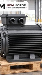
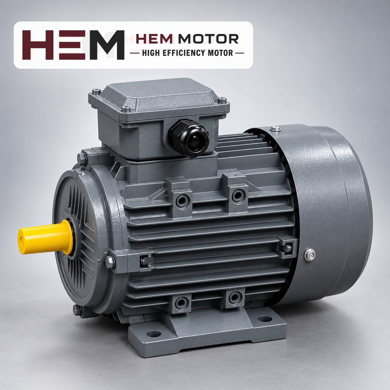

On a textile winding machine, what determines the motor choice is how the load changes as the roll grows. If fabric is wound at constant speed and constant tension, when the roll diameter doubles the torque on the winding shaft also doubles, while the shaft speed halves. That is why the drive is selected not for a single operating point but for the torque at the largest diameter and the speed at the smallest diameter together.
This article deals with centre-driven winders that wind fabric or nonwovens onto a shaft. In surface (drum-contact) winding, the drive drum turns at constant speed and the roll diameter does not directly affect the motor; the issue there is different.
How do torque and speed change as the roll grows?
In centre winding, two quantities are to be held constant: line speed (the fabric's advance in metres per minute) and fabric tension. In this case:
- Torque = tension × roll radius. As the roll grows, torque rises in direct proportion to diameter.
- Speed = line speed ÷ roll circumference. As the roll grows, shaft speed falls in inverse proportion to diameter.
- Power = torque × speed. Since the two effects balance each other, winding power is roughly constant and independent of diameter.
The last point has an important consequence: although winding power is constant, the motor must deliver it over a wide speed range. An induction motor, however, reaches the highest power at which it can carry its rated torque only at its rated speed. When it delivers the same torque at low speed, its output power falls. So the motor power is calculated not from the actual power need of winding, but from the speed at which it must deliver the torque of the largest roll.
Build-up ratio: the most critical design figure
The ratio of the full roll diameter to the empty core (shaft or cardboard tube) diameter is called the build-up ratio. This ratio directly determines how wide the motor's operating speed range will be.
| Hypothetical case | Empty core diameter | Full roll diameter | Build-up ratio | Motor speed range |
|---|---|---|---|---|
| Thin fabric, small roll | 100 mm | 300 mm | 1:3 | from rated down to one third |
| Heavy fabric, large roll | 150 mm | 900 mm | 1:6 | from rated down to one sixth |
The table is hypothetical and only shows the logic of the ratio. If the gearbox ratio is chosen so that the motor turns close to its rated speed while reaching line speed on the empty core, then when the roll is full the motor runs at its rated speed divided by the build-up ratio, at the highest torque. At 1:6, this means continuous operation close to full torque at around one sixth of rated speed.
How are the motor and gearbox selected together?
The selection sequence can be set up as follows:
- From line speed and empty core diameter, find the highest speed of the winding shaft.
- From tension and full roll radius, find the highest torque on the winding shaft. The tension value comes from the machine manufacturer or the process data; it should not be guessed.
- Set the gearbox ratio so that the highest shaft speed corresponds approximately to the motor's rated speed.
- Find the motor torque by dividing the highest shaft torque by the gearbox ratio and gearbox efficiency; this value must stay below the motor's rated torque.
- Add an acceleration margin: a full, heavy roll needs extra torque when accelerating from standstill to line speed.
The motor's rated torque can be read from the product data. For example, the 3 kW 100L2-4 model with a rated speed of 1,450 rpm has a rated torque of 19.8 Nm, the 4 kW 112M-4 model 26.3 Nm, and the 5.5 kW 132S-4 model 36 Nm. The full torque table is in our electric motor torque table article.
For wider build-up ratios, a 6-pole motor can also be considered. For example, the 3 kW 132S-6 model delivers 29.6 Nm at a rated speed of 968 rpm; compared with the 4-pole model of the same power, it provides higher torque and a lower starting speed, but its frame is larger (132S).
You can compare models from the standard range and current prices on the buy electric motors page.
Low-speed inverter operation and cooling
On centre winders, speed variation is almost always provided by a frequency inverter. HEM Motor's three-phase ranges are suitable for speed control with a frequency inverter; according to the general rule in the inverter question, an external fan may be required if the motor is to run at low speed with full torque for long periods, a dv/dt or sine filter is considered if the drive-motor cable is long, and these conditions are stated with the order.
A winding machine is exactly one of the applications where this "long periods of high torque at low speed" condition occurs. As the roll approaches full, the motor slows down but its torque rises; the cooling fan mounted on its own shaft blows less air as speed falls. On a machine with a high build-up ratio and a long time spent at full roll, make sure to discuss the external fan option in the order. Lint and fibre build-up in a textile environment further weakens cooling; keeping the fan cover clean should be part of the maintenance plan.