English
 Français
 Türkçe
 Español
 Русский

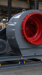
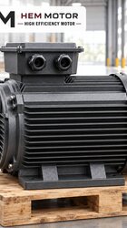
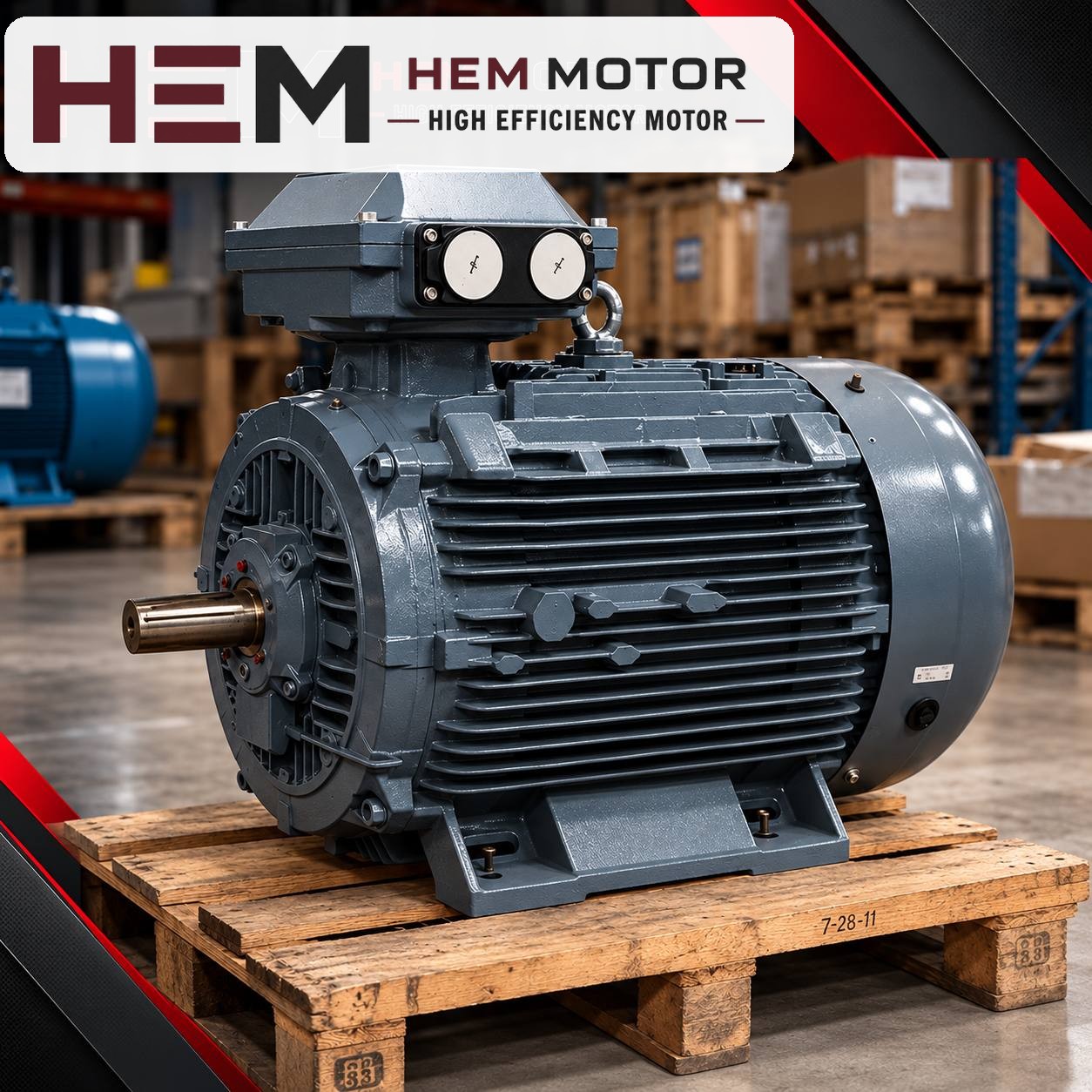

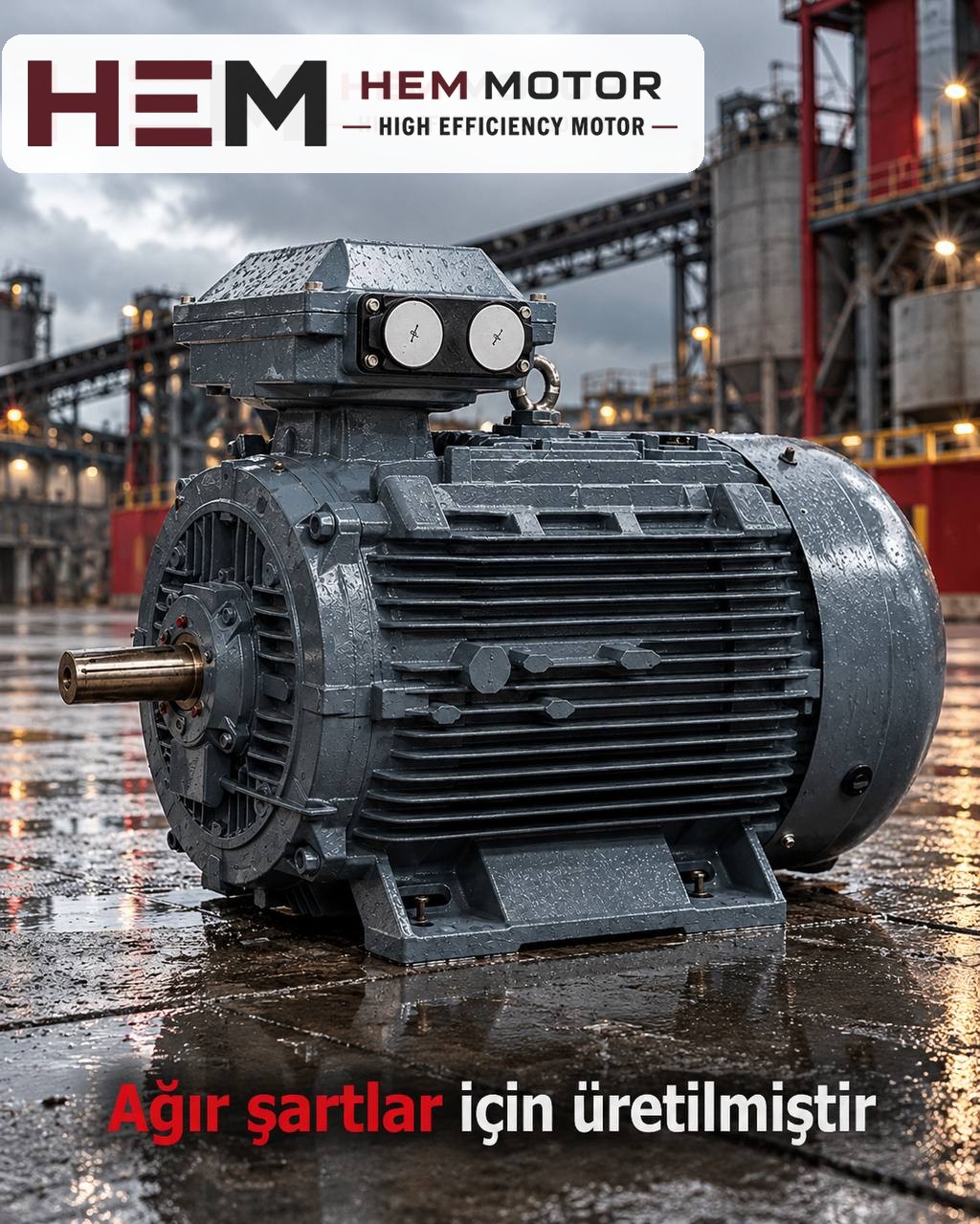
In an asphalt plant, the dryer drum is a large, inclined, rotating cylinder that heats cold aggregate and removes its moisture. A burner fires at one end, and the aggregate is lifted by flights inside the drum and carried through the flame and hot gas as it moves towards the other end. The motor that turns the drum works right next to this hot and dusty structure. In this article we cover drum drive arrangements, how to keep the motor away from heat and dust, load sharing on drives with more than one motor, and the information needed for a replacement.
Two ways to turn a dryer drum
Dryer drums are usually turned with one of two drive arrangements. Which one is used determines the number of motors, the mounting arrangement and what to check when replacing.
Trunnion (friction wheel) drive
The drum rests on four support rollers through steel riding rings wrapped around its shell. Two or four of these rollers are driven, each connected to its own motor-gearbox unit, and turn the drum by friction. In this arrangement there are several motors on a single drum, and the motors share the same load.
Chain or girth gear drive
A chain sprocket or a large girth gear fixed around the drum is turned through a pinion by a single motor-gearbox unit. The drive is applied at one point; that is why the motor and gearbox are of higher power and the pinion alignment becomes critical.
Whatever the arrangement, the motor power has been selected by the plant manufacturer according to the diameter and length of the drum, the amount of aggregate inside it and its rotational speed. When replacing, this information is read from the old motor's nameplate. Power is not guessed from the machine's name or capacity.
Heat and dust: the motor's real enemies
On the burner side, the drum shell gets quite hot during operation and radiates heat to its surroundings. The motors are usually positioned under or beside the drum, right next to the rollers. This layout makes several conditions mandatory for a standard motor to be able to run at its nameplate values.
- No direct exposure to heat: A standard motor is not positioned close to the hot drum shell or the burner area. There must be sufficient distance or a heat shield between the motor and the hot surface.
- Cooling air must be free: Self-ventilated (IC411) motors are cooled by the ambient air they draw in through the fan cover. The area in front of the fan cover must be clear, and the air drawn in must not be hot gas. You can find the difference between cooling methods in the IC411 and IC416 cooling article.
- Ambient temperature: The values on the motor nameplate apply to a given ambient temperature and altitude. If the temperature is high at the point where the motor will run, state this in the order; in such a case the power may need to be reassessed.
- Mineral dust: Aggregate dust and fine dust escaping the filter build up on the finned frame. The models HEM Motor offers are IP55 protected with class F insulation; IP55 protects against dust ingress, but a dust layer on the frame surface still weakens cooling. Regular cleaning should be part of the maintenance plan.
Load sharing on drives with more than one motor
On a trunnion drive, two or four motors turning the same drum together call for extra care when replacing. When only one of the motors is replaced, the new motor must work in harmony with the others.
- All motors must have the same power, number of poles and rated speed. Motors with different rated speeds connected to the same rollers do not share the load equally; one becomes overloaded while another runs lightly loaded.
- Gearbox ratios and roller diameters must remain the same. If the gearbox on one side has been changed, this should also be stated in the order.
- The thermal protection of each motor is set separately according to the rated current on its own nameplate. For protection selection, see the thermal relay and fuse selection article.
- At the first start, the direction of rotation of each motor is checked separately. A single motor running in reverse works against the others and strains the rollers and the gearbox.
Starting, stopping and speed adjustment
A dryer drum rotates with high inertia; setting a loaded drum in motion is heavier than keeping it turning. At start-up, the aggregate inside the drum may have collected on one side.
- Starting method: The choice between star-delta, direct-on-line, soft starter or frequency inverter is made on site by an engineer, depending on the drum's inertia, the possibility of a loaded start and how well the supply can withstand the starting current.
- Rotation after shutdown: Many plant manufacturers require the drum to keep turning after the burner goes out until the shell has cooled. This means the drive motor also runs during shutdown; the precaution to take against a power cut is a matter of plant design.
- Speed adjustment: If the drum speed is to be adjusted with a frequency inverter, the general statement on our site applies: our three-phase series are suitable for speed control with a frequency inverter; for long periods of full-torque operation at low speed an external fan may be needed, and if the cable between drive and motor is long a dv/dt or sine filter is considered; these conditions are stated with the order. Details are in the frequency inverter question.