English
 Français
 Türkçe
 Español
 Русский

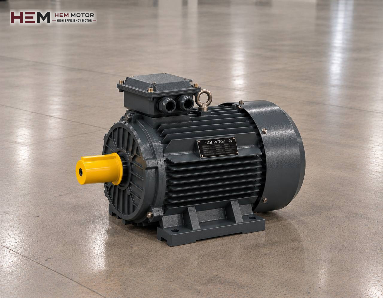
In most quarries the machine that takes the large blasted blocks from the truck dump hopper and releases them into the primary crusher at a steady rate is a pan-type (apron) feeder. Overlapping steel pans travel slowly on two chains, and the entire hopper load rests on them. This page covers the electric motor that drives the feeder; for the other machines in the plant see stone crushing plant electric motors.

How does an apron feeder carry quarry rock?
The feeder body consists of two endless chains, heavy pans bolted to the chains and the rollers that support them. As the head sprocket turns, the pans are pulled forward from under the hopper and tip the rock into the crusher. Several metres of material can sit on the pans, and every truck adds fresh blocks on top of this pile.
The feeder therefore needs a very different drive from a belt conveyor. Speed is very low while the turning torque on the shaft is high. The motor cannot deliver such a low speed on its own; a high-ratio gearbox sits in between, and the real task is converting motor power through the gearbox into a slow but forceful rotation.
Starting under a full hopper: the moment that loads the motor
The heaviest moment for a feeder is the first movement. When a plant stopped overnight is restarted in the morning, the hopper is usually full; the pans must be moved together with the weight of the rock mass on them and the material rubbing against the hopper walls. That means a breakaway torque clearly higher than the torque drawn when running at constant speed.
The load is not smooth during operation either. Blocks falling from the truck hit the pans; the impact is taken mainly by the pans and the impact beams below them, but short torque peaks reach the motor through the chain. When the crusher fills up and the feeder is stopped and restarted, the same breakaway load occurs again. Motor power is set on the basis of the starting torque given by the machine manufacturer and the worst loading case; on an existing feeder the nameplate of the old motor is the most reliable starting point.
Speed control: not starving or choking the crusher
A primary crusher works efficiently when a regular amount of rock enters its mouth. Overfeeding chokes the crusher, underfeeding wastes capacity. In modern plants the apron feeder speed is therefore often adjusted with a frequency inverter; the crusher motor current is monitored and the feeder speeds up or slows down accordingly. The inverter also gives a soft but high-torque start under a full hopper and allows a short reverse run to clear a jam.
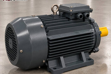
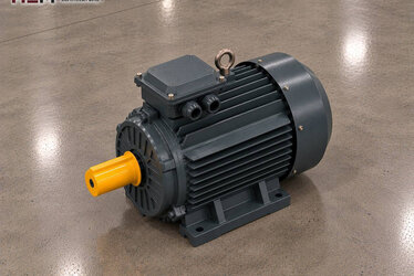
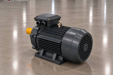
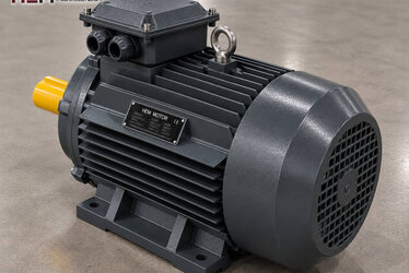
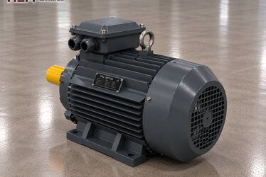
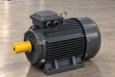
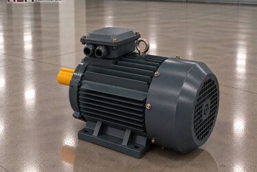
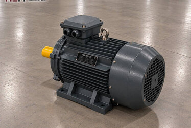
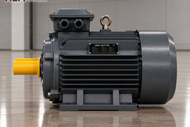
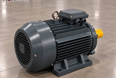
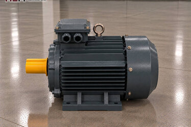
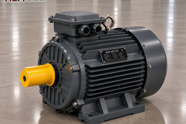
HEM three-phase motors can be driven by a frequency inverter. On a feeder the motor often turns well below rated speed at full torque; in this duty the shaft-mounted fan may not provide enough cooling and a separately powered external fan may be needed. If the cable between motor and inverter is long, a dv/dt or sine filter should be considered. State these details in your order; the subject is also covered on the inverter-compatible motors page.
Some large feeders are hydraulically rather than electromechanically driven: the electric motor turns a hydraulic pump, and a hydraulic motor coupled to the sprocket pulls the pans. In this arrangement the motor is selected according to pump flow and pressure; details are on the hydraulic pump motors page.
Gearbox, coupling and connection layout
Two common layouts are seen in electromechanical drives. In the first, motor and gearbox sit on a separate base with a flexible coupling between them, and the gearbox output is connected to the sprocket shaft. In the second, the gearbox is mounted directly on the sprocket shaft (shaft-mounted type) and held to the frame by a torque arm; the motor is carried on top of or beside the gearbox. In both cases the motor must have a flange and shaft size that match the gearbox input.
HEM motors are available as foot-mounted B3, flange-mounted B5 and B14, foot-and-flange B34 and B35 and in vertical positions, depending on frame size; the flange and shaft size that suit the gearbox are confirmed together at the time of order. Gearbox selection and ratio belong to the machine builder's calculation; for the motor side the electric motors for gearboxes page is a guide. On inclined feeders the device that prevents rollback is usually on the gearbox side.
Conditions under the hopper: dust, water and temperature
An apron feeder is usually outdoors, and rock dumped by trucks raises heavy dust. HEM motors have IP55 protection; this rating limits harmful dust ingress and splashing water. However, a thick dust layer covers the cooling fins, so the motor frame and fan cover must be cleaned periodically. Where rain or wash water hits the motor directly, a protective roof is advisable; a standard IP55 motor is not designed for high-pressure water washing.
In motors that stand idle for long periods in winter, moisture can condense inside the frame; an anti-condensation heater is an order option. On a speed-controlled feeder a PTC thermistor can also be requested to monitor winding temperature. Bearing lubrication intervals and chain tension are maintenance items that prevent a large share of motor failures.
Example HEM models and selection table
Apron feeders generally run with a 4- or 6-pole motor and a gearbox. For example, the 7.5 kW 1000 rpm cast iron 160M-6 model delivers 73.8 Nm at a rated speed of 970 rpm. On a larger feeder the 15 kW 1000 rpm cast iron 180L-6 model produces 146.5 Nm at 978 rpm. If the gearbox input calls for the 1500 rpm class, the 7.5 kW cast iron 132M-4 or 18.5 kW cast iron 180M-4 models are options worth checking.
| Feeder situation | Load seen by the motor | Value to check | Example HEM model |
|---|---|---|---|
| Small quarry, short feeder | Breakaway torque with full hopper | Gearbox input speed, starting torque | 160M-6, 7.5 kW |
| Large hopper, heavy primary feed | High continuous torque, falling block impact | Shaft power, duty conditions | 180L-6, 15 kW |
| Inverter speed-controlled feeder | Full torque at low speed | External fan, PTC, cable length | 132M-4, 7.5 kW |
| Long, inclined feeder | Incline component and continuous load | Rollback prevention, flange size | 180M-4, 18.5 kW |
| Hydraulically driven feeder | Pump flow and pressure | Pump data, operating cycle | According to pump manufacturer data |
The models in the table are examples; the final selection depends on machine load, required speed, mounting and operating conditions.
What information to send with a quotation request?
So that we can propose the right motor quickly, send the machine layout of the feeder and the following data: required power (kW), speed (rpm), site voltage, mounting type (foot, flange or gearbox-mounted), gearbox input dimensions, whether an inverter will be used and the quantity required. If you are replacing an old motor, sending a photo of the nameplate is a sufficient start.
All frame and power options are listed with current prices on our shop page. To send your request via WhatsApp or by phone, use the numbers on the contact page; motors held in stock are shipped from our warehouse in Türkiye.
Frequently Asked Questions
Which pole number suits an apron feeder?
Both 4-pole and 6-pole motors are found on these feeders. What decides is the input speed the gearbox was selected for. The input speed on the existing gearbox nameplate and the pole number of the old motor should be kept.
Why does the feeder motor trip at start-up?
Breakaway torque under a full hopper is high. Overload setting, starting method and motor power should be checked together. Star-delta starting reduces torque and may therefore be insufficient on a heavy feeder; an inverter gives a more controlled start.
Does continuous running at very low speed on an inverter damage the motor?
During long running at low speed and full torque, cooling from the shaft-mounted fan decreases. In this case an external fan and PTC winding temperature monitoring should be requested with the order.
Can you also supply the motor of a hydraulically driven feeder?
Yes, we supply the standard three-phase motor that turns the pump of the hydraulic unit. Selection requires the flow, pressure and shaft power data given by the pump manufacturer.