English
 Français
 Türkçe
 Español
 Русский

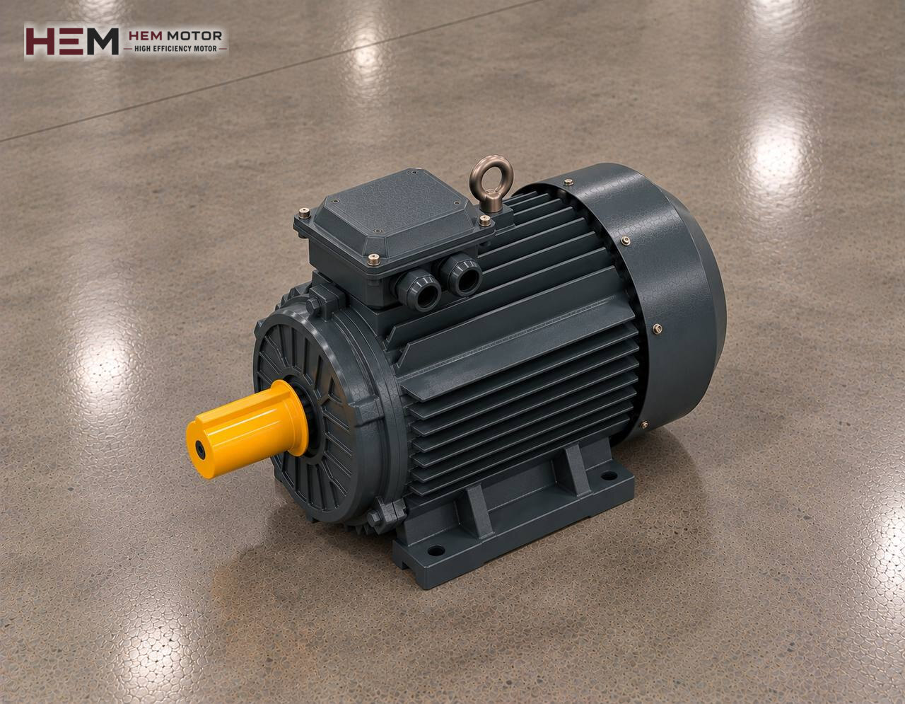
In a roll crusher the rock is drawn between two cylinders turning towards each other, squeezed and broken by compression; in single-roll types a toothed cylinder presses the rock against a fixed breaker plate. The gap between the two rolls sets the product size, so the machine gives a controlled-size output with little fines. It is used on coal, clay, marl, salt, gypsum and soft limestone, and also at the second or third stage of aggregate lines. This page focuses on the electric motors that turn the rolls; for the rest of the plant see the electric motors for crushers and stone crushing plants page.

Two rolls, two motors: the drive arrangement
In double-roll crushers each roll usually has its own motor. One motor turns the roll in fixed bearings, the other the movable roll held by springs or a hydraulic cylinder. On some machines a single motor drives both rolls through long-tooth gears or a chain, but on large machines two independent drives are more common. In that case the order asks for both motors to have the same power, speed and frame; this also makes spares and maintenance easier.
If the rolls turn at the same speed, the material is broken mainly by pressure. In some types the rolls are deliberately run at different speeds; the speed difference adds a tearing effect while squeezing the material. This difference is obtained with the pulley ratio, the gearbox ratio or a drive. Which difference to apply belongs to the machine design; the job on the motor side is to build a drive arrangement that keeps this difference stable.
Low roll speed, high torque
The peripheral speed on the roll surface is much lower than the rotor speed in hammer or impact crushers. The difference between the motor's rated speed and the roll speed is therefore large, and a belt and pulley, a gearbox or both are placed between them. Because high crushing force is required at low roll speed, the torque transmitted to the roll is also high; when choosing the motor, the torque required at the roll shaft and the transmission ratio are assessed together with the power.
In a belt and pulley arrangement a foot-mounted 4- or 6-pole motor is common; the pulley ratio sets the roll speed, and the belt slips briefly at the moment of a jam, softening the shock. In a geared arrangement the motor is connected to the gearbox by feet or flange, and the gearbox input speed is chosen according to the motor speed. The gearbox ratio and output torque are the gearbox maker's data. The general framework for geared drives is described on the electric motors for reducers page.
Character of the load: continuous squeezing and jam moments
Under steady feeding, the load on a roll crusher is fairly continuous and balanced. What strains the motor is a large block suddenly arriving at the feed opening or an uncrushable foreign object. The springs or hydraulic system holding the movable roll then retract and let the piece pass; but during this short time the torque on the roll shaft rises and motor current peaks.
These peaks should not trip the motor unnecessarily, yet the motor must be protected in a real jam. The thermal relay is set to the rated current on the nameplate; with persistent jams a current monitoring relay stops the feed. A magnet or metal detector placed ahead of the rolls prevents uncrushable iron from entering the machine in the first place.
Starting, simultaneous running and direction
A roll crusher does not take as long to start as a hammer crusher, because although the rolls have large inertia, their speed is low. Even so, the machine should be started empty and the feed opened only after both motors reach full speed. On two-motor machines, bringing the motors in at the same time or in sequence with a short delay spreads the starting current on the supply.
Because the two rolls must turn towards each other, one motor runs opposite to the other. The direction of a standard three-phase motor is reversed by swapping two supply leads; at commissioning, the direction of each motor should be confirmed by a short run before the belts are fitted. If a drive is to be used to change the speed difference or the feed rate, our three-phase range is suitable for running on a frequency inverter. If the motor will run at low speed with full torque for long periods, a separate cooling fan comes into question, and if the drive cable is long, a dv/dt or sine filter; state this in the order. Details are on the inverter-compatible motors page.
Sticky material, dust and roll maintenance
A roll crusher often works with sticky material such as damp clay and marl. Material building up on the roll surface narrows the gap and increases load and current; scraper adjustment therefore directly affects motor load as well. With dry coal and limestone, fine dust comes to the fore and builds up on the motor's cooling fins.
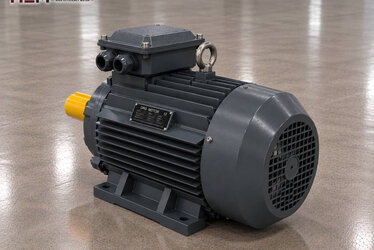
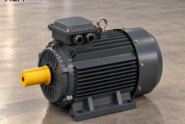
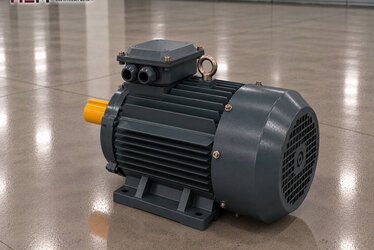
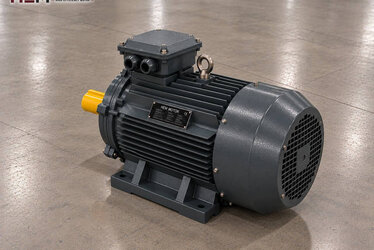
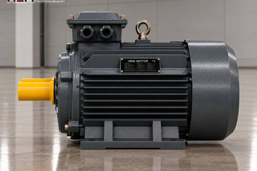
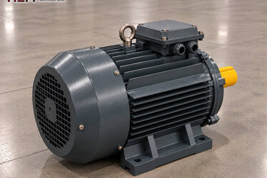
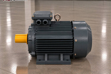
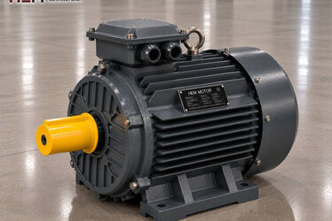
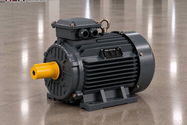
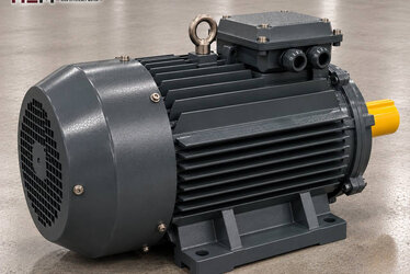
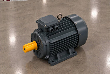
HEM three-phase motors have IP55 enclosures and class F insulation; regular cleaning of the fan and fins, checking the base bolts and following belt tension help the motor run for a long time. As the rolls wear, their surfaces are rebuilt or replaced; after this work, pulley alignment and belt tension should be checked again. An anti-condensation heater for motors that stand idle for long periods, and PTC or PT100 sensors to monitor winding temperature, are order options.
Sample motors per roll
| Roll crusher type | Transmission | Key selection point | Sample HEM motor (per roll) |
|---|---|---|---|
| Small double-roll crusher | Belt and pulley, 6-pole | Roll speed, pulley ratio | 15 kW 1,000 rpm 180L-6 |
| Medium coal and clay crusher | Geared, 6-pole | Torque at the roll shaft, gearbox input speed | 30 kW 1,000 rpm 225M-6 |
| Secondary roll crusher in an aggregate line | Belt and pulley, 4-pole | Jam current, metal separator | 37 kW 1,500 rpm 225S-4 |
| Large toothed roll crusher | Geared, 4-pole | High torque, matching the two motors | 90 kW 1,500 rpm 280M-4 |
These models are for guidance; the motor for each roll is decided according to the machine load, roll speed, transmission ratio, mounting and operating conditions. For example, the 180L-6 delivers 146.5 Nm rated torque at 978 rpm and the 225M-6 delivers 292.3 Nm at 980 rpm; the 90 kW 280M-4 has a service factor of 1.15.
Information to send when requesting a quote
When asking for a motor for your roll crusher, send the machine type and number of rolls, the power (kW) and speed (rpm) required per roll, supply voltage, mounting (foot-mounted or flanged to a gearbox), transmission arrangement, starting method, the directions of rotation of the motors and the total quantity. If you have nameplate photos of the existing motors, selecting an equivalent becomes much faster. Foot, flange and combined mountings are offered according to frame; shaft and flange dimensions are confirmed in the order.
Models and current prices are in our shop, and larger powers in the cast iron frame motors section. To reach us by WhatsApp or phone, use the contact page.
Frequently Asked Questions
Must the two motors on a double-roll crusher be the same model?
It may not be technically mandatory, but it is recommended. Two motors with the same power, speed and frame share the load evenly, the spare motor is a single type and there is no confusion over parts during maintenance.
Is the roll speed difference set by the motor?
On most machines the speed difference is fixed by the pulley or gearbox ratio. If the difference is to be changed in operation, each motor can be driven by its own frequency inverter; the difference to apply is set according to the machine maker's recommendation.
Why does the roll crusher motor show sudden current peaks?
When a large block or an uncrushable piece reaches the feed opening, the torque on the roll shaft rises until the movable roll retracts. These short peaks are normal; if they repeat often, the feed size, scraper adjustment and metal separator should be checked.
How is the direction of rotation of the two roll motors confirmed?
At first commissioning, each motor is run briefly with no load before the belts or coupling are connected, and its direction is compared with the marking. If the direction is wrong, two phase leads are swapped; the transmission is then connected and a no-load trial is run.