English
 Français
 Türkçe
 Español
 Русский

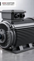
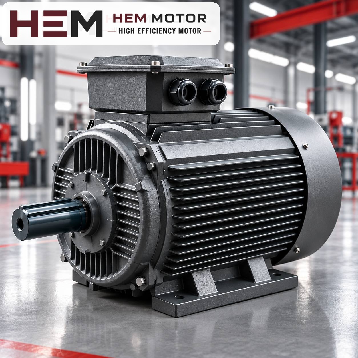

The motor power for a surface irrigation pump is found by adding a margin to the shaft power calculated from the pump's flow and head; the speed is the speed the pump was designed for and is not changed when the motor is chosen. In short, the power is read from the operating point in the field and the speed from the pump's nameplate. This article explains how the calculation is done and how the variable conditions specific to irrigation affect the choice.
Here, "surface type" means pumps installed outside a well, beside a pond, canal, tank or shallow water source, with the motor standing on dry ground. Submersible and deep-well pumps that go down into the water require a different motor type; a standard-frame motor is not used in their place.
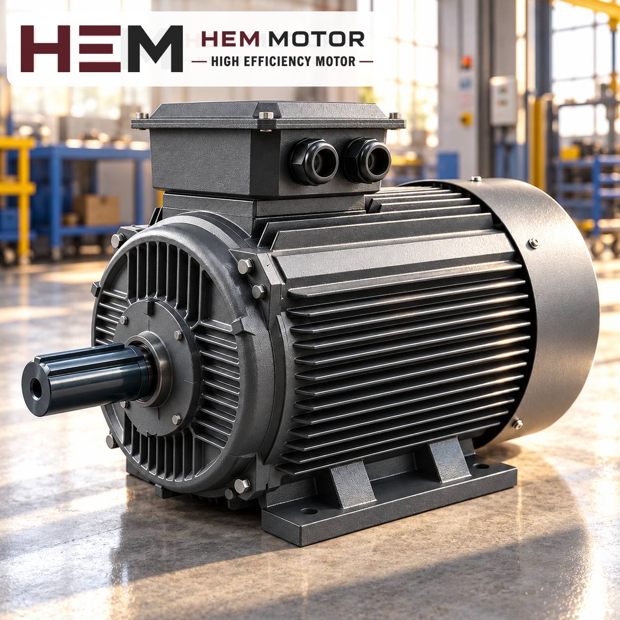
Power calculation: flow, head and pump efficiency
The hydraulic power the pump transfers to the water depends on the product of the flow and the total head. The power the motor must deliver to the pump shaft is found by dividing this value by the pump efficiency. For water, the practical formula is:
Shaft power (kW) = Flow (m³/h) × Total head (m) / (367 × pump efficiency)
The 367 in the formula is a constant derived from the density of water, gravitational acceleration and unit conversion. Pump efficiency is the value read at the operating point on the catalogue curve; in small irrigation pumps this ratio is lower than in large pumps. If you do not have the curve, take the efficiency from the pump manufacturer's data, not from a guess.
Total head is not just the slope of the field. Take the following into account together:
- Suction lift: The vertical distance from the water level to the pump axis. As the pond level drops at the end of summer, this value increases.
- Static discharge head: The elevation difference from the pump to the highest point of the line.
- Pipe losses: Friction in the line length, pipe diameter, elbows, valves and filters. On long, narrow lines this item can exceed the elevation difference.
- End pressure: The operating pressure needed for the sprinkler head or drip system, converted into metres of water column and added.
How is the motor margin determined?
The calculated shaft power is not directly the motor power. In a centrifugal pump, the power drawn rises as the flow increases. In an irrigation line, when the number of open sectors changes, when a pipe bursts or while the line is first filling, the pump shifts to the right of the curve and draws more power than calculated. For this reason, the motor should be chosen not only for the design point but for the highest flow point that can occur in the field.
- Look at the "power" curve on the pump curve and find the highest value within the operating range for your impeller diameter.
- Choose the first standard motor power above this value. If the pump manufacturer gives the motor power on the nameplate, use that as the basis.
- HEM Motor models of 75 kW and above have a service factor of 1.15; this is a safety margin and is not used to undersize the motor.
An oversized motor is not a solution either. The pump delivers the same water, the motor runs at partial load, and the starting equipment, cable and panel grow unnecessarily.
Speed: stick to the value on the pump's nameplate
In a centrifugal pump, flow changes in direct proportion to speed, head with the square of speed and power with the cube of speed. Because of this relationship, fitting a motor of a different speed to the same pump completely changes the operating point: a pump designed for 3,000 rpm gives about half the flow and a quarter of the head with a 1,500 rpm motor. The reverse overloads both the motor and the pump.
Speed selection is therefore made together with pump selection. A large share of surface irrigation pumps run with two-pole (3,000 rpm synchronous) motors; some pumps that need high flow at low head are four-pole. The value you will see on the motor nameplate is the rated speed: on two-pole motors, about 2,930–2,955 rpm is read under load.
If the pressure in the field must vary by sector, a frequency inverter can be used. Our three-phase series are suitable for speed control with a frequency inverter; for long periods of operation at low speed with full torque, a separate fan may be needed, and if the cable between drive and motor is long, a dv/dt or sine filter is considered; these conditions are stated with the order. For details, see the question on inverter use.
Hypothetical calculation examples
The values below are hypothetical; they are not taken from a real site and only show the logic of the calculation. In each example the pump efficiency is assumed to have been read from the curve.
| Scenario | Flow | Total head | Pump efficiency | Shaft power | Possible motor |
|---|---|---|---|---|---|
| Garden and greenhouse line | 30 m³/h | 35 m | 0.65 | ≈ 4.4 kW | 5.5 kW, 3,000 rpm |
| Sprinkler, medium field | 60 m³/h | 50 m | 0.70 | ≈ 11.7 kW | 15 kW, 3,000 rpm |
| Long line at high elevation | 80 m³/h | 60 m | 0.72 | ≈ 18.2 kW | 22 kW, 3,000 rpm |
In the second row the calculation gives 11.7 kW. An 11 kW motor falls below this value; considering also that the flow will increase while the line first fills, 15 kW is the appropriate choice. In the third row, 18.5 kW is very close to the calculated value; since the suction lift increases when the pond level drops, the next power up, 22 kW, has been preferred. In actual selection, the highest power value on the pump curve is used as the basis.