English
 Français
 Türkçe
 Español
 Русский

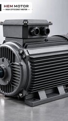
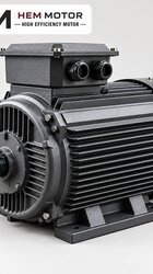
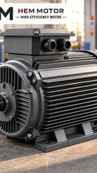
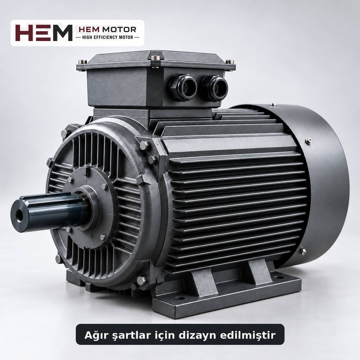

The motor of a chemical transfer pump is selected according to the conditions of the environment, not of the pump. The pump's power and speed are determined by the fluid's density, viscosity and the pump type; the motor's frame, degree of protection and installation location are determined by vapour, splashing, washdown water and the risk of an explosive atmosphere. A standard IP55 motor is a suitable starting point in a closed, ventilated pump room without a hazardous area classification; in areas with heavy vapour or declared hazardous zones, the scope of a standard motor is exceeded.
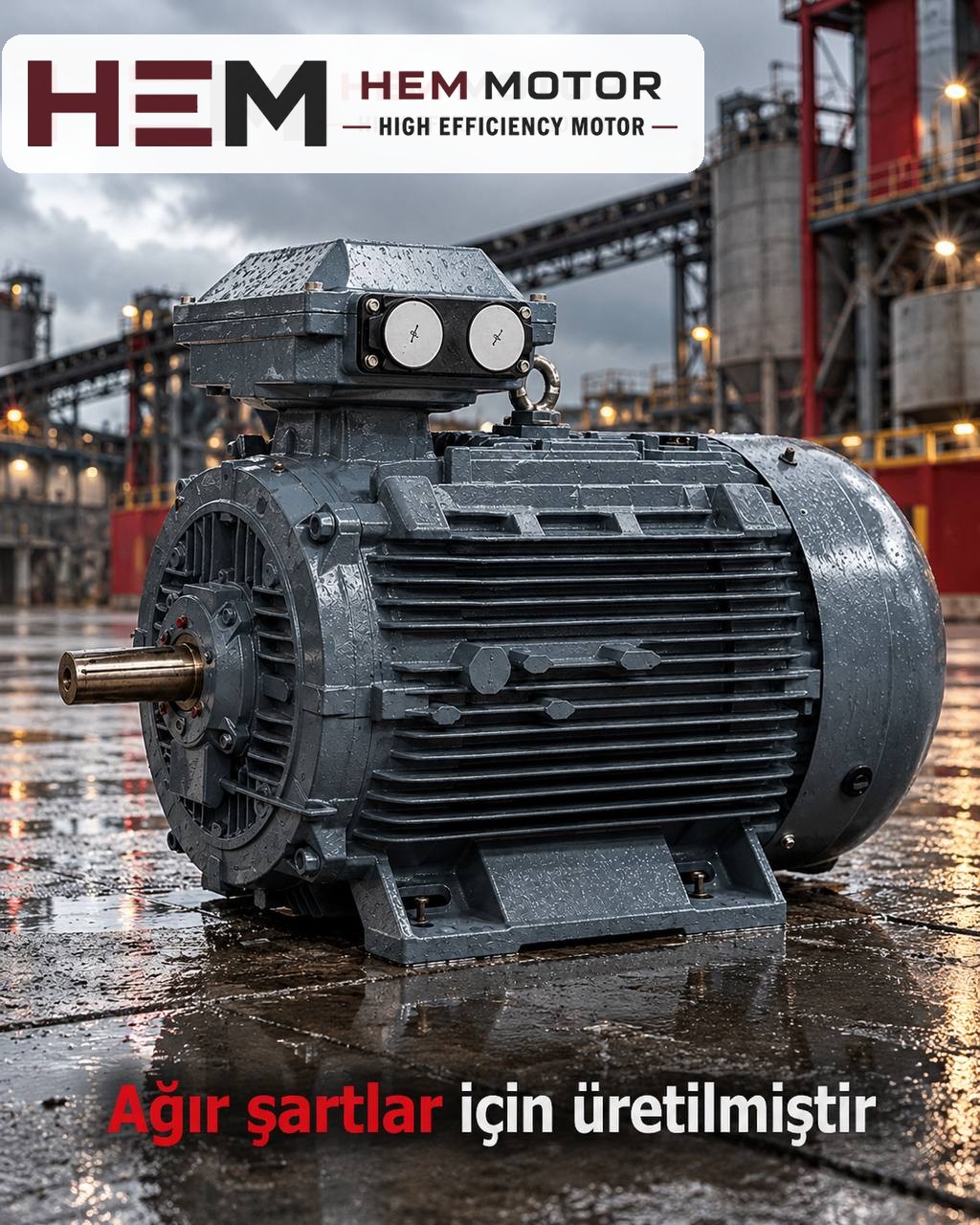
How do fluid conditions affect motor power?
The power value in a pump catalogue is usually given for water. If the chemical fluid differs from water, the load seen by the motor changes too:
- Density: In a centrifugal pump, shaft power rises in direct proportion to the fluid's density. A pump handling an acid about 30% denser than water needs about 30% more power at the same flow and head. A motor selected for water may not cover this difference.
- Viscosity: As the fluid thickens, the efficiency of a centrifugal pump falls and the power required rises. With products that thicken in the cold, the motor is under the most strain at the first start.
- Pump type: Positive displacement pumps (gear, lobe, diaphragm, screw) demand more torque as pressure rises and quickly overload the motor if the line is closed. On these pumps, the relief valve and motor protection are considered together.
- Dry running: If the pump runs dry when the tank empties, the motor load falls; however, the pump seal or magnetic coupling may be damaged. This is not a motor problem but a level control problem.
Practical rule: ask the pump manufacturer for the power value for the actual fluid. When replacing, if the old motor ran without problems, the same power and number of poles is a safe starting point.
Environmental conditions: what does IP55 cover and what does it not?
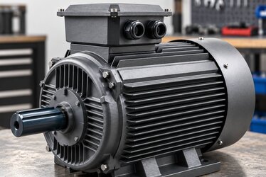
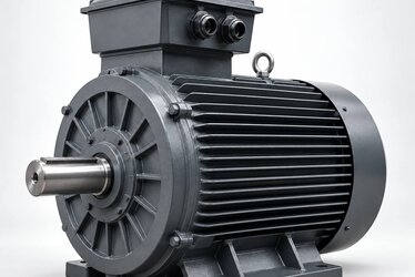
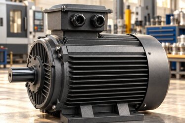
The models HEM Motor sells come with IP55 protection and class F insulation. IP55 means protection against dust deposits and resistance to water jets from any direction. In a chemical plant this class is generally sufficient in the following cases:
- The pump room is closed and ventilated, and chemical vapour does not constantly accumulate around the motor.
- The floor is washed but the motor is not directly exposed to a pressurised water jet.
- Occasional drips or splashes may reach the motor but do not accumulate on it.
In the following conditions, however, IP55 alone is no guarantee and must be stated separately with the order:
- Continuous acid or alkali vapour: Over time, vapour affects the paint, terminal box gasket, shaft seal and cable entries. In this case, the first measure is to place the motor away from the source of the vapour or to ventilate the area.
- High-pressure washing and direct washing with chemical cleaning agents.
- Outdoor operation in sun and rain; the top of the motor must be protected.
- High ambient temperature or the motor being placed close to a heated tank surface. The ambient temperature is stated with the order.
A cast iron frame is more resistant to mechanical impact, but it does not mean a "chemical-resistant motor". Whatever the frame material, in a corrosive environment it is the paint, gaskets and connection points that really need protecting.
Explosive atmospheres: the limit of a standard motor
Areas where chemicals giving off solvent, alcohol, fuel or flammable vapour are transferred are often classified as hazardous zones. A motor used in these zones must have a special design suited to that zone and be certified accordingly. A standard IP55 motor does not meet this duty; this duty requires a special motor. It may fall outside the scope of the standard series in HEM Motor's 2026 catalogue; ask us with the nameplate and application details.
Zone classification is the plant's responsibility. If you are unsure, ask the plant's health and safety unit for the zone information before selecting the motor. A standard motor can be considered for a non-flammable acid or base; it is not considered for a flammable solvent.
Connection and mounting by pump type
Chemical transfer pumps are usually connected to the motor in one of three ways:
- Magnetic drive pumps: There is no mechanical connection between the motor shaft and the pump impeller; power is transmitted through magnets. The motor is connected to the pump lantern with a standard IEC flange and shaft end. The flange size (B5/B14) and shaft diameter must be the same as on the old motor.
- Coupled horizontal pumps: Pump and motor sit on a common baseplate and a B3 foot-mounted motor is used. Shaft height and foot hole spacing must match the old motor, and the coupling alignment must be redone.
- Vertical tank pumps: The motor stands on top of the tank with the shaft facing down. In this layout the motor may be directly above the vapour; besides vertical mounting, the effect of vapour is also assessed.
At HEM Motor, B3, B5, B14, B34, B35 and vertical V1/V3/V5/V6/V15 mounting arrangements are offered according to the frame; the flange size is confirmed with the order. For frame and shaft dimensions, see the 2D technical drawings.