English
 Français
 Türkçe
 Español
 Русский

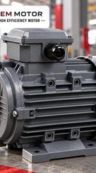
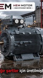
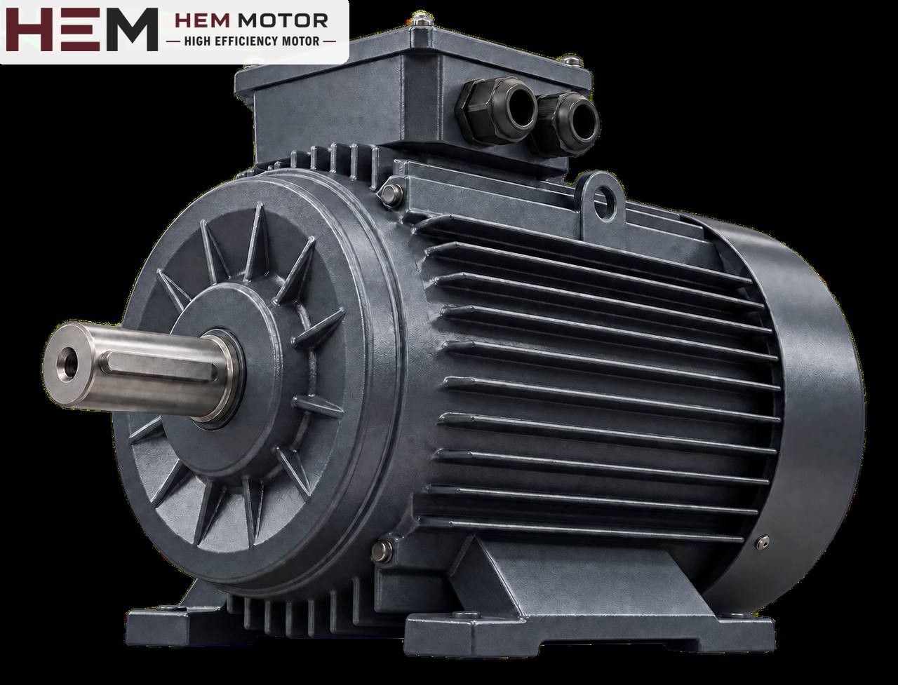

When selecting a ball mill motor, the real challenge is not running but starting: the ball and material charge inside the rotating drum forms a large unbalanced mass that the motor must lift at the very first moment. The motor must be able to carry this load throughout the start, be correctly connected to the gear or belt arrangement that turns the drum, and be started with a method suited to starting under load. This article focuses on the drives of small and medium ball mills found in cement, mining, ceramic and lime plants.

How does the load arise in a ball mill?
A ball mill is a horizontal drum containing steel balls and the material to be ground. As the drum turns, the balls rise with the drum wall to a certain height and then roll and fall, grinding the material. The motor's main job is to keep this mass of balls and material constantly lifted to one side. The fuller the mill and the larger the drum, the higher the required torque.
The character of this load is steady: once the mill reaches speed, the power demand does not fluctuate much. At the moment of starting, however, the motor has to move the stationary mass and force it to rise with the drum. That is why, for a mill motor, starting torque and starting time are as important as rated power.
Drum speed is also decisive. The grinding action of the balls depends on the drum turning at a certain fraction below critical speed. This speed is set by the mill manufacturer; the motor is selected together with the drive ratio that reaches this speed.
Drive arrangements: girth gear, belt and central drive
Different drive arrangements are used depending on mill size. How the motor is selected depends on the arrangement:
- Girth gear and pinion: A large ring gear is fitted around the outside of the drum. The motor turns the pinion through a gearbox and coupling, and the pinion turns the girth gear. This is common on medium and large mills.
- Small belt-driven mills: On laboratory and small production mills, the motor may turn the drum or a countershaft by belt.
- Central (end) drive: Motor and gearbox are connected to the drum axis at one end.
- Roller mills: On small ceramic and paint mills, the drum turns on two drive rollers; the motor turning the rollers transfers the load by friction.
In the girth gear arrangement, the gearbox ratio between motor and pinion reduces motor speed to drum speed. In this arrangement, the gearbox input connection, coupling alignment and the position of the motor relative to the gearbox are the main points checked when choosing a spare motor.
Starting under load: why is it critical?
A ball mill always starts loaded; the balls stay inside. This means the motor accelerates against a high initial resistance. During the start current stays high and heat builds up in the winding. The longer the start, the more this heat increases.
The frozen charge problem
If the mill stands still for a long time, especially in wet grinding, the material and balls can pack together at the bottom of the drum into a single mass. On starting, this mass rises with the drum and at some point suddenly breaks away and falls. This fall delivers a heavy blow to the drum, liners, gear and bearings. On large mills, a slow-turning (inching) drive separate from the main drive is used to reduce this risk; the mill is first turned slowly with this device to loosen the charge.
The inching drive usually consists of a separate small motor, a gearbox and a clutch or locked connection. This small motor is also assessed separately according to its own nameplate; some arrangements use a brake motor, which is not within the standard series.
Starting method
- Direct-on-line starting: Provides the highest starting torque but puts high shock on the supply and the mechanics. It is seen on small mills where the supply allows it.
- Star-delta: Reduces starting torque; it may be insufficient for starting a loaded mill and is generally not preferred.
- Soft starter: Reduces current and shock; but since torque also falls at reduced voltage, its setting must be made carefully for a loaded mill.
- Frequency inverter: Can provide high starting torque with low current and also allows the drum speed to be adjusted.
Historically, slip-ring (wound-rotor) motors and starting resistors have been used on large mills. This type of motor differs from a standard squirrel-cage motor; if the existing mill uses this arrangement, this duty requires a special motor and may fall outside the scope of the standard series in HEM Motor's 2026 catalogue. Consult us with the nameplate and panel details.
Drive, cooling and protection
If the mill is run on a drive, the following general statement applies: our three-phase series are suitable for speed control with a frequency inverter; for long periods at low speed with full torque an external fan may be needed, and if the cable between drive and motor is long a dv/dt or sine filter is considered; these conditions are stated with the order. For a load such as a mill that needs constant high torque, this should be stated specifically if the speed is to be reduced well below the rated value. The general framework is in the question on inverter use.
On the protection side, the thermal setting must be chosen to withstand the long starting time. PTC or PT100 temperature sensors embedded in the winding can be requested as an option with the order; these sensors directly monitor heating that current-based protection might miss. Details on protection devices are explained in our article on thermal relay and fuse selection.
Mill plants are very dusty; the motor's fan cover grille and frame fins should be cleaned regularly. If the ambient temperature is high, it is stated in the order.