 English
 Français
 Türkçe
 Español
 Русский

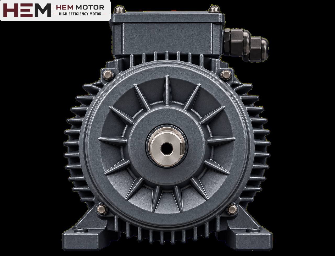

When selecting the motor for a metal shredder, the real deciding factor is not the type of material being shredded but the path by which the impact reaches the motor. On a low-speed twin-shaft shredder the impact travels straight back to the shaft through the gearbox; on a hammer mill the flywheel absorbs the impact but lengthens the start; on a hydraulically driven machine the motor hardly feels the impact at all. So the drive arrangement must be understood first, and the motor then selected for that arrangement.
Three drive arrangements, three different motor loads
Machines that shred scrap metal, swarf, aluminium profiles, white goods or cable may look similar from the outside, but they contain different drive architectures. The load affecting the motor changes completely with this architecture.
| Drive arrangement | Effect of the impact on the motor | Critical point for the motor |
|---|---|---|
| Electric motor + gearbox (twin or four-shaft, low speed) | A piece caught in the blades reflects torque back to the motor through the gearbox | Frequent reversing, torque peaks, gearbox and coupling protection |
| Electric motor + belt + flywheel (hammer mill) | The flywheel smooths sudden impacts; the motor sees the average load | Time to accelerate a high-inertia rotor |
| Electric motor + hydraulic pump + hydraulic motors | The impact is absorbed in the hydraulic system and limited by the pressure relief | Pump power and continuous operation, hydraulic unit conditions |
Even with two machines of the same power, deciding on a motor replacement without knowing which arrangement each uses is risky. The machine nameplate and drive diagram are the first documents in motor selection.
Torque peaks on geared low-speed shredders
On a twin-shaft shredder, the bladed shafts turn at a few tens of revolutions per minute. The motor usually drives these shafts through a planetary or helical bevel gearbox; some machines have a separate motor-gearbox group for each shaft. When a hard piece gets between the blades, the shaft slows down and torque rises instantly.
Automatic reversing
The controls of these machines stop the shafts when motor current exceeds a certain value, reverse them briefly and then try forward again. Every change of direction means a new start in which the motor draws high current. When working with material that jams frequently, dozens of reversals per hour can occur; this determines motor heating far more than the rated power does.
- State the estimated number of reversals per hour in the order; frequent reversing is assessed separately in motor selection.
- Direction should be changed with the motor stopped; sudden reversing while running puts a heavy load on the winding and gearbox.
- On machines with a frequency inverter, reversing is done with a ramp and current is limited. Our three-phase series are suitable for speed control with a frequency inverter; for long periods of full-torque operation at low speed an external fan may be needed, and if the cable between drive and motor is long a dv/dt or sine filter is considered.
Mechanical protection elements
To keep torque peaks away from the motor and gearbox, the drive line may include a torque limiter, a shear-pin coupling or a hydrodynamic (fluid) coupling. A fluid coupling lets the motor accelerate unloaded first and absorbs sudden impacts by slipping. These elements belong to the machine builder's design; when replacing the motor, make sure they are in place and working.
Flywheel and starting time on hammer mills
On hammer-type metal crushers the rotor and its hammers form a large mass; on most machines an additional flywheel is also fitted. During operation this inertia smooths the impacts: the rotor slows slightly with each strike and the motor accelerates it again in between. The motor thus carries a load close to the average rather than the peaks.
The price is paid at start-up. Bringing a heavy rotor from standstill to full speed can take a long time, and the motor draws high current throughout. Every motor has a permitted starting time and number of starts per hour. If the rotor's moment of inertia (J) and the required starting time are known, it can be calculated whether the motor can handle this start; ask the machine builder for these data and pass them on to us.
- Start with the machine empty; open the feed only after the rotor has reached full speed.
- With star-delta starting, the low torque in star lengthens the acceleration of a heavy rotor; the changeover time is set accordingly.
- Repeated start attempts heat the motor; after a failed start, wait for the motor to cool down.
Motor selection on hydraulically driven machines
On some shredders the bladed shafts are turned by hydraulic motors; the electric motor only drives the hydraulic pump. In this arrangement the impact is limited by the hydraulic pressure relief, and the motor mostly runs at constant speed with a fluctuating but smoothed load. Motor power comes from the pump flow and operating pressure; power is not determined from the machine's name.
On this type of machine the motor works on the tank of the hydraulic unit with a pump bell housing and coupling. Mounting arrangements (B3, B5, B14, B34, B35 and vertical V1/V3/V5/V6/V15) are offered according to the frame and the flange size is confirmed with the order. For an overview of hydraulic applications, see the hydraulic pump motors page.
Whichever drive arrangement you have, if the power and speed of the existing motor are known, review suitable HEM Motor models and current prices.