English
 Français
 Türkçe
 Español
 Русский

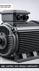
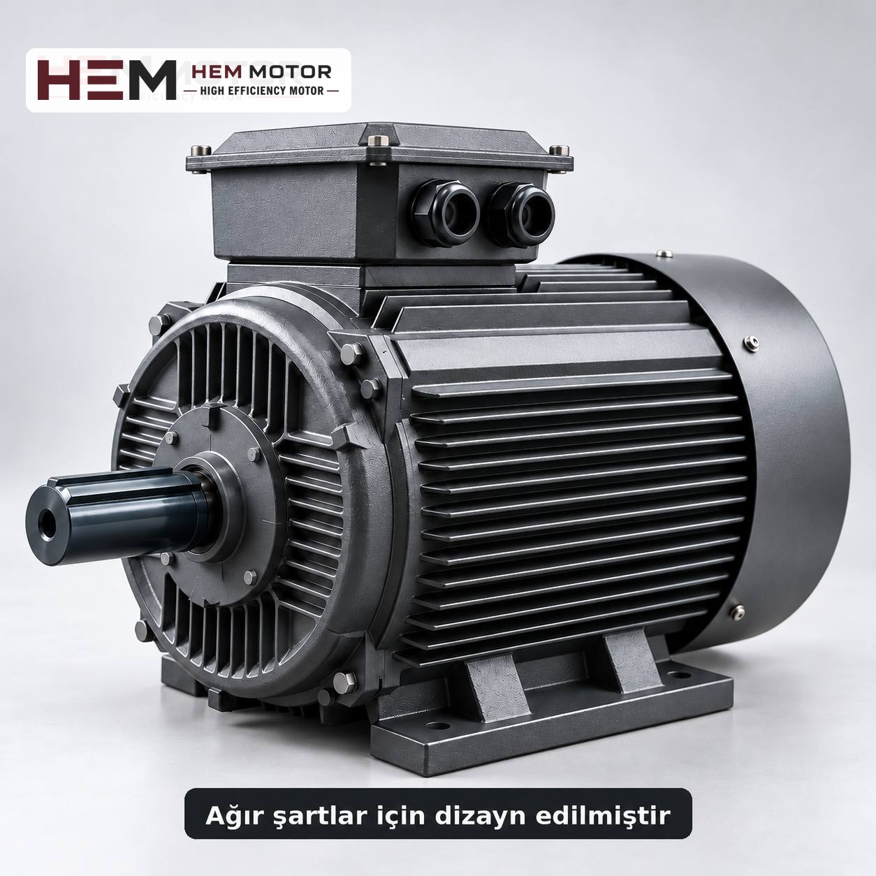

An impact crusher breaks stone not by squeezing it but by striking it at speed. In horizontal shaft types (HSI), a heavy rotor carrying blow bars spins at high speed; stone falling from the feed opening hits these bars, is thrown against the impact aprons in the crusher housing and shatters. In vertical shaft types (VSI), material is fed into the centre of a fast-spinning rotor and flung outwards against an anvil ring or a bed of material. In both types, what the motor is really working against is the rotor: its mass, its speed and the amount of material passing through it. This article explains from which angles the rotor load should be read when choosing a motor for an impact crusher, and what to watch for during a replacement.
The rotor load has three parts
Thinking of the load seen by the motor of an impact crusher as a single number is misleading. The same crusher can draw very different currents with different feeding.
- Load of turning the rotor: Even a rotor spinning empty needs some power because of air resistance, bearing friction and belt losses. This base load is present as long as the machine runs.
- Crushing load: As stone strikes the rotor, the rotor slows slightly and the motor makes up for this loss of speed. As the feed rate and the hardness of the stone increase, the average power demand rises. Uneven feeding shows up as constant fluctuation in the motor current.
- Impact peaks: When a large block or an uncrushable piece (a bucket tooth, broken steel) enters the rotor, a short, sharp load peak occurs. The rotor's inertia absorbs part of this peak; the rest reaches the motor through the belts and the motor shaft.
The sum of these three components becomes the motor power set by the crusher manufacturer. The manufacturer makes this calculation based on rotor diameter, rotor speed, feed size and the required capacity. Motor power is not guessed from the machine's name or the size of its feed opening; on an existing crusher, the starting point is the old motor's nameplate and the manufacturer's documentation.
Rotor speed, pulley ratio and number of poles
One of the main factors that determine product size in an impact crusher is the peripheral speed of the rotor. As rotor speed rises, impact intensity increases and the product becomes finer; as speed falls, the product becomes coarser. This speed is the combined result of the motor speed and the pulley ratio.
- On large horizontal shaft crushers the motor is usually 4-pole, and the rotor is driven by belt at a lower speed than the motor. Some plants also use 6-pole motors.
- Changing the number of poles directly changes the rotor speed and therefore the product grading. If the new motor has a different number of poles from the old one, the pulleys are recalculated; this decision is taken together with the crusher manufacturer.
- In plants where rotor speed is frequently changed for process reasons, a frequency inverter can be used. The general statement on our site is: our three-phase series are suitable for speed control with a frequency inverter; for long periods of full-torque operation at low speed an external fan may be needed, and if the cable between drive and motor is long a dv/dt or sine filter is considered; these conditions are stated with the order. For details see the frequency inverter question.
Starting and stopping with a heavy rotor
An impact crusher rotor turns with very large inertia for its size. While bringing this rotor from standstill to operating speed, the motor draws high current for a long time. Always starting empty, that is, not opening the feed before the rotor reaches full speed, is a basic operating rule.
- Starting method: On a high-inertia rotor, star-delta starting can lengthen acceleration, while direct-on-line starting can cause a noticeable voltage drop on the supply. Which method will be used (direct, star-delta, soft starter or frequency inverter) is decided on site by an engineer, taking into account rotor inertia and the plant's supply capacity.
- Starting frequency: Every start of a heavy rotor heats the motor. Starts repeated at short intervals do not give the motor a chance to cool down. The number of starts per day should be stated in the order.
- Stopping: When power is cut, the rotor keeps turning for a long time. Maintenance doors are not opened until the rotor has stopped completely, and the motor must not be re-energised while the rotor is still turning.
The protection device must not trip during a long start, yet must protect the motor in a real overload. The thermal relay and fuse selection article provides guidance on choosing the protection class.
Uncrushable material and the effect of impact loads on the motor
A piece of steel entering the crusher brakes the rotor instantly. At that moment the belts slip or break, the rotor's blow bars may be damaged, and the motor receives a very high, short torque shock. Crusher manufacturers usually limit this risk with a metal separator on the feed line (a magnetic separator or metal detector) and safety devices in the housing.
What matters from the motor's point of view is that these shocks are not an operating condition to be absorbed by a standard motor, but a fault condition that must be prevented by equipment. Frequently repeated shocks cause fatigue in the shaft, key, bearings and pulley connection. During replacement, the motor pulley, keyway and belt tension should also be checked.
In a B3 foot-mounted arrangement the motor is fixed to a tensioning slide, and belt tension is adjusted with the slide. Mounting arrangements are offered according to the frame as B3, B5, B14, B34, B35 and vertical V1/V3/V5/V6/V15; the flange size is confirmed with the order. On vertical shaft crushers, the motor position and belt layout vary with the manufacturer; whether the motor will stand horizontally or vertically must be stated. Shaft, foot and flange dimensions are in the 2D technical drawings and the 2026 catalogue.