English
 Français
 Türkçe
 Español
 Русский

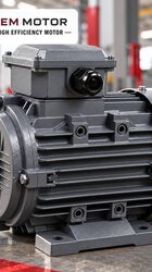
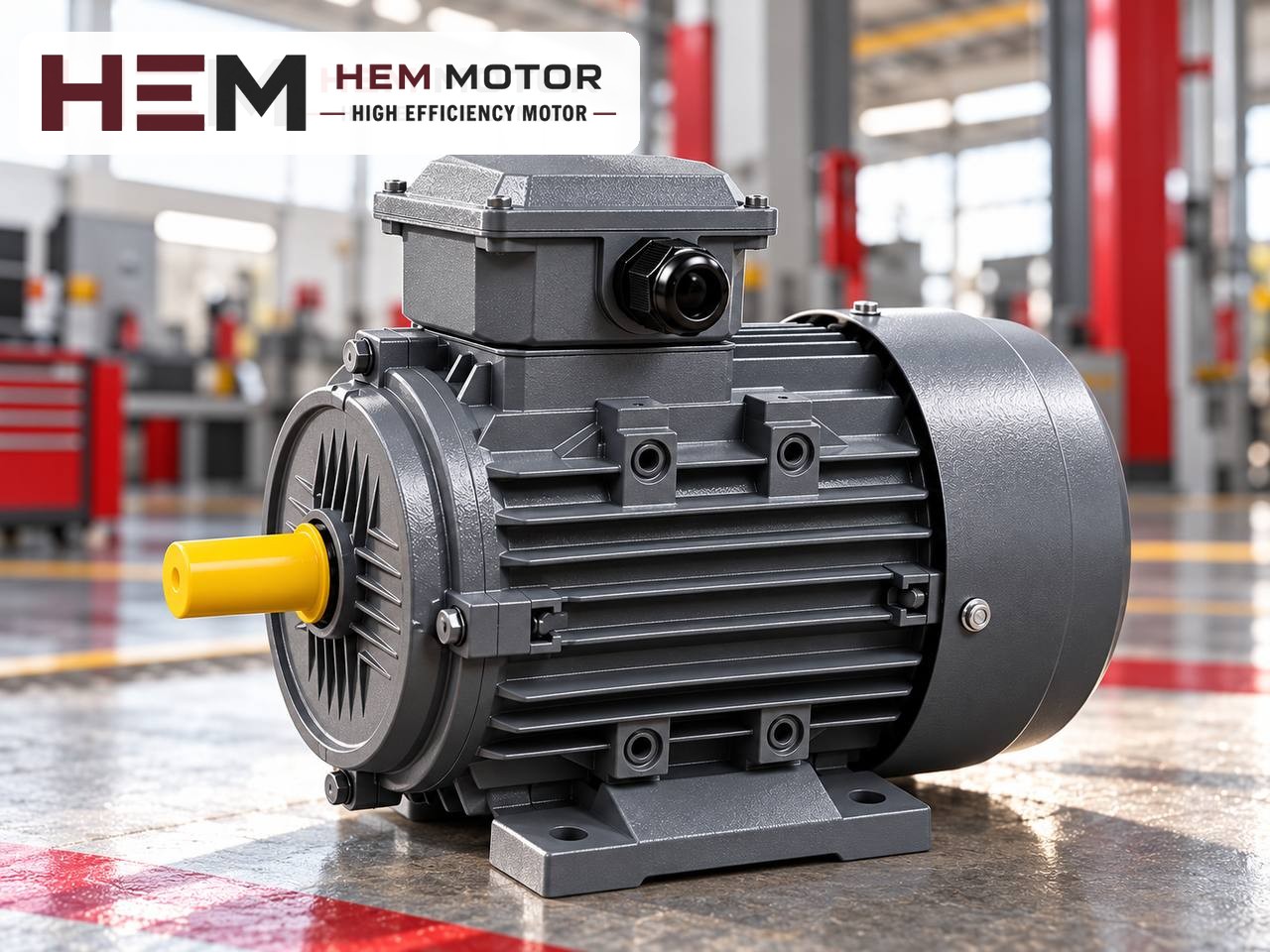

On a screw sand washer, the motor and gearbox are selected together: the motor supplies the power, and the gearbox produces the torque needed to turn the screw slowly through water and sand. What matters on this machine is that the screw turns at a very low speed, that sand settling at the bottom of the tank buries the screw after a stop, and that the motor works in a place with constant splashes of water and slurry. Below we go through these three topics and motor-gearbox matching step by step.

How does a sand washer work?
A screw sand washer consists of a long screw turning inside an inclined tank. Sand and water are fed into the lower part of the tank. As the screw turns, it carries the sand up the slope; meanwhile clay, silt and fine dust flow out over the overflow weir with the water. The sand that reaches the upper end of the tank is discharged after giving up part of its water.
This job needs the screw to turn slowly: a fast-turning screw churns the water, mixes fine material back into the sand and spoils dewatering. The right screw speed is set by the machine manufacturer. Twin-screw models with two screws side by side are also common for higher capacity.
The bucket-wheel washer, another type used for sand washing, has a different drive arrangement; this article focuses on the screw type.
Drive train: motor, belt and gearbox
The low screw speed is achieved by greatly reducing the roughly 1,450 rpm coming from the motor. The three arrangements most often seen on site are:
- Shaft-mounted gearbox and belt: The gearbox is slid onto the end of the screw shaft and fixed to the tank with a torque arm. The motor sits on a base above or beside the gearbox and drives it by V-belt. The pulley ratio allows small adjustments to screw speed.
- Flange-mounted motor and gearbox: The motor is connected directly to the gearbox input flange. The layout is compact, but there is no pulley option for speed adjustment.
- Foot-mounted motor, coupling and gearbox: Motor and gearbox stand on a common frame with a flexible coupling between them. This is found on large machines.
On twin-screw machines each screw may have its own motor and gearbox, or a single motor may feed two gearboxes through an intermediate shaft. Knowing which arrangement is used is the first step in choosing a spare motor.
Gearbox ratio and screw speed calculation
Screw speed is found by dividing the motor speed first by the pulley ratio and then by the gearbox ratio: screw speed = motor rated speed × (motor pulley ÷ gearbox pulley) ÷ gearbox ratio.
A hypothetical calculation
The numbers are chosen only to show the method. Consider a 4-pole motor (rated 1,465 rpm), a 160 mm motor pulley, a 250 mm gearbox pulley and a 1:40 shaft-mounted gearbox. The speed at the gearbox input is 1,465 × 160 ÷ 250 ≈ 938 rpm, and the screw speed is 938 ÷ 40 ≈ 23 rpm. If a 6-pole motor (about 970 rpm) were used in the same arrangement, the screw would drop to about 15 rpm; this difference changes washing and dewatering behaviour.
The conclusion is clear: the spare motor must have the same number of poles as the old one. If the screw speed needs to change, this is done with the pulley ratio and within the range recommended by the manufacturer.
Matching gearbox power and motor power
The gearbox also has a power and output torque limit. Moving the motor up one power size only makes sense if it can be done without exceeding this limit. The ratio, input power and service factor on the gearbox nameplate should be read before starting motor selection. General information on geared applications is on the electric motors for gearboxes page.
Starting with settled sand
The hardest moment on a sand washer is the first movement after a long stop. When the machine stops, the sand in the tank settles in the water and buries the lower part of the screw. When the screw is to be turned again, the motor has to move this packed mass of sand. A starting torque noticeably higher than the normal running load is required.
The main operating measures taken for this situation are:
- Stopping after emptying: After the feed is cut, the screw is kept turning for a while; the machine is stopped with less sand in the tank.
- Lifting device: On some machines the lower end of the screw can be raised by a hoist or hydraulic system. Lifting the screw out of the settled sand before starting protects the motor.
- Loosening with water: Adding water to the tank before starting loosens the sand and reduces resistance.
- Suitable starting method: With star-delta starting the starting torque drops, so the motor may not start with a buried screw. A soft starter or controlled start with a drive may give better results; the torque requirement is taken into account when choosing the method.
If the protection keeps tripping during starting, the solution is not to bypass it but to review why the sand settles and the starting method. Repeated forcing wears the motor winding and the gearbox gears.