Mounting Compatibility of the Electric Motor on Marble Grinding and Polishing Machines

Mounting Compatibility of the Electric Motor on Marble Grinding and Polishing Machines

On marble grinding and polishing machines, the motor turns the head that carries the abrasive stones and often runs vertically with the shaft pointing down. For this reason, the first question in a replacement is not power, but which surface and which shaft the motor uses to connect to the machine. Two motors with the same kW rating give completely different results when the flange and shaft of one fit the head and those of the other do not. In this article we explain how to check mounting compatibility step by step on grinding and polishing lines.

How the motor sits on the grinding head

Grinding and polishing machines are built in different designs, from single-head bridge types to multi-head line machines. The motor is usually arranged in one of three ways:

  • Vertical flange-mounted, shaft down: The motor is bolted to the head body by its flange and the shaft turns the stone plate directly or through a coupling. This vertical position is referred to as V1.
  • Through a gearbox: The motor sits on the input flange of a right-angle or inline gearbox; the head speed is reduced by the gear ratio.
  • Belt transmission: The motor is attached beside or above the head on a separate slide and the head spindle turns in its own bearings.

Whatever the arrangement, the pressing force of the head and the vibration of the stone reach the motor in some way. Knowing whether this load is carried by the motor's bearings or by the head's own bearings determines the outcome of the replacement.

Special shaft and flange: the limit of a standard motor

On marble machines, a large share of the motors are made specifically for the machine: an extended or stepped shaft, special bearings chosen for heavy axial load, a non-standard or long flange, and sometimes a shaft end on which the stone plate is mounted directly. A standard motor can be used directly only in the following case:

  • The diameter, length and keyway of the shaft end are the same as the standard IEC values for the frame size.
  • The flange has the dimensions of a standard B5 (large, through holes) or B14 (small, tapped holes) flange; the spigot diameter and pitch circle are the same as on the head side.
  • The shaft carries a coupling, a pulley or a gearbox input, not the plate.
  • The pressing force of the head does not bear directly on the motor bearings.

If one of these conditions is missing, a special motor is needed instead of a standard one. In that case, photograph the nameplate, the shaft end and the flange of the motor on the head and ask us. Simply calling a flange "B5" or "B14" is not enough for compatibility; flanges with the same name can have different dimensions depending on the frame size.
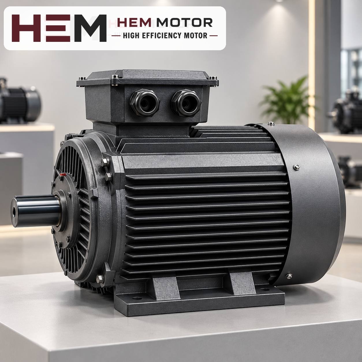
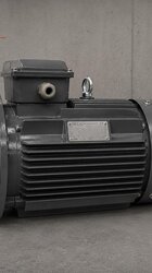
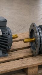
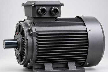
Three-phase motor on a grey base showing the flange and shaft side
Before the replacement, the flange face and the shaft end are compared (representative image).

Points to watch in vertical mounting

Our site does not keep a separate mounting list for each model. Foot-mounted B3, flange-mounted B5 and B14, combined B34 and B35, and vertical V1, V3, V5, V6 and V15 arrangements are provided according to frame size; the flange size is verified together at the order stage. If the motor on the grinding head will run shaft down, be sure to state this in the order. Vertical operation also has some practical consequences:

  • Axial load: If the weight of the head and plate hangs on the shaft, the bearings must be selected for the axial direction. If this load exceeds the scope of a standard motor, special bearings are needed.
  • Direction of water and slurry: With the shaft down, water tends to run along the shaft towards the front end shield. The condition of the front seal and the water deflector on the head are important.
  • Fan cover: On a shaft-down motor the fan cover faces upwards; slurry and debris falling on it must not block the air inlet. A protective canopy is considered if needed.
  • Terminal box orientation: In vertical mounting, having the cable entry face downwards prevents water from filling the box.

For broader information on choosing a vertical motor, see the vertical mounting article and the mounting arrangements question.

Wet environment and IP55

In grinding and polishing, the stone surface is watered continuously; the area around the machine is covered with fine stone slurry. The protection class of HEM Motor models on sale is IP55. This class covers dust ingress that would damage the frame and light water spray reaching the motor from different angles. Immersing the motor in water, washing it with pressurised water or leaving it in slurry is outside this class. On lines that are pressure-washed, do not aim at the motor directly. If water splashing is heavy, state it in the order; such conditions may exceed the scope of a standard motor. On heads with vibration and impacts, cast iron frame models offer a stiffer construction.

Prices and technical data are on the product pages; choose a model and order online.

Determining power and speed

Suggesting a single power value from the machine type is not correct; the stone diameter, head pressure, number of plates, type of stone processed and daily operating time of the line all play a part. In a replacement, the soundest reference is the old motor's nameplate. On grinding heads, speed directly affects the mark the head leaves on the surface, so the number of poles and the rated speed must be kept. For example, on a 4-pole motor's nameplate you will see a value such as 1,450 or 1,460 rpm; this is the on-load equivalent of the 1,500 rpm synchronous speed.

If the head speed is to be changed with a drive, note this: our three-phase series are suitable for speed adjustment with a frequency inverter. If the motor will turn at low speed with full torque for long periods, a separate external fan may be needed; if the cable from the drive to the motor is long, a dv/dt or sine filter is considered. It is enough to state these operating conditions in the order. For more, see the inverter question.

Example: geared polishing head

The following flow is hypothetical; it does not describe a real customer application. Suppose that on a multi-head polishing line, the motor of each head sits vertically on the input flange of an inline gearbox. The failed motor's nameplate reads 5.5 kW, 1,460 rpm and a 132S frame.

  • Inspect the connection: The motor shaft enters the gearbox input bore with a key; the plate is on the gearbox output. The motor bearings do not carry the plate pressure.
  • Compare the flange: If the spigot diameter and pitch circle at the gearbox input match a standard flange for a 132 frame, a standard motor can be considered. If they do not, a special flange is needed.
  • Match the model: These values correspond to the 5.5 kW 1,500 rpm cast iron 132S-4 model: 4 poles, 1,460 rpm, IEC 132S, 400/690 V (Δ/Y), 10.7 A rated current.
  • Declare vertical operation: The order states the V1 (shaft down) position and the flange type; the flange size is confirmed with the order.

If smaller heads on the same line have 4 kW motors, the 112M-4 (1,450 rpm, IEC 112M, 7.95 A) can be compared. For larger heads, there is the 132M-4 model for 7.5 kW (1,460 rpm, IEC 132M, 14.3 A). If the frame size changes, the flange and shaft dimensions change too; they must be compared again with the gearbox input. Shaft and flange dimensions are in the 2D technical drawings and the 2026 catalogue. The current price is on each model's own product page.

Mounting compatibility checklist

  • What is on the shaft end: plate, coupling, pulley, gearbox input?
  • Are the flange type and size the same as their counterpart on the head or gearbox?
  • Does the motor run vertically, shaft down or shaft up?
  • Do the pressure and weight of the head bear on the motor bearings?
  • From which direction do water and slurry reach the motor, and which way does the terminal box face?

Information to send with a quotation request

So that we can match the grinding and polishing motor correctly, send the following:

  • The nameplate of the removed motor; a photo in which power, speed, current and frame size can be read
  • Close-up photos of the flange from the front and of the shaft end
  • Mounting position (e.g. V1 shaft down) and connection type
  • Mains voltage, starting method and whether a drive is used
  • How much water and slurry there is on the head

You can see three-phase models that may suit grinding and polishing heads, together with their current prices, on our shop page. If the shaft or flange is not standard, send the motor nameplate and its photos; let us determine together whether a special motor is needed. For other matters, reach us through our contact page.

HEM Motor Models Related to This Article

The cards show example models related to the topic. A suitable motor is not chosen by power alone: compare speed, voltage, mounting, shaft and connection dimensions on the product page; if unsure, send a photo of the existing motor’s nameplate on WhatsApp.

5.5 kW 1500 rpm Cast Iron Frame Electric Motor 132S-4

132S-4

5.5 kW · 1500 rpm

  • Cast iron frame · IEC 132S
  • 1460 rpm · IP55
  • Mounting: B3 foot; flange (B5/B14/B35) depending on frame — confirmed with the order

US$339.83 (€303.28)

View product
4 kW 1500 rpm Cast Iron Frame Electric Motor 112M-4

112M-4

4 kW · 1500 rpm

  • Cast iron frame · IEC 112M
  • 1450 rpm · IP55
  • Mounting: B3 foot; flange (B5/B14/B35) depending on frame — confirmed with the order

US$252.76 (€225.57)

View product
7.5 kW 1500 rpm Cast Iron Frame Electric Motor 132M-4

132M-4

7.5 kW · 1500 rpm

  • Cast iron frame · IEC 132M
  • 1460 rpm · IP55
  • Mounting: B3 foot; flange (B5/B14/B35) depending on frame — confirmed with the order

US$392.38 (€350.17)

View product

Similar Articles