English
 Français
 Türkçe
 Español
 Русский

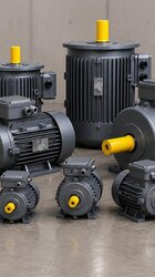
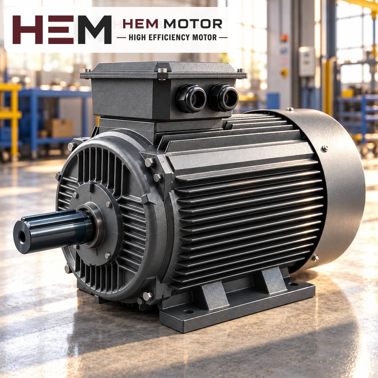

When replacing a car lift motor, two checks cause more trouble than power and speed: how the hydraulic pump is attached to the motor and the duty regime in which the lift runs the motor. A motor with the same kW and the same speed on its nameplate is useless on the lift if its shaft end does not fit the pump or if the direction of rotation is connected the wrong way. This article explains, step by step, what to check on site when renewing the motor of an electro-hydraulic lift unit.
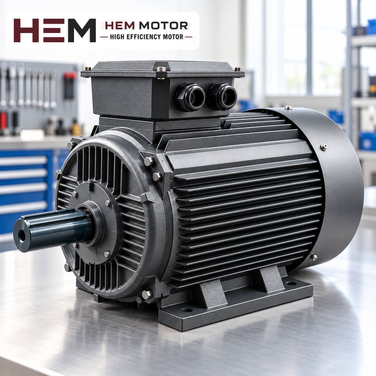
On a lift, the motor runs only while raising
On most two-post, four-post and scissor lifts, motion comes from a hydraulic power unit. When the button is pressed, the motor drives the gear pump, the pump pushes oil into the cylinder and the vehicle rises. During lowering the motor usually stops; once the lowering valve opens, the oil returns to the tank under the weight of the vehicle. So the motor's job is to run close to full load for a short time on every lift, under a pressure that increases towards the end.
This intermittent operation may be stated on the motor nameplate as the duty type. S1 means continuous duty, S2 short-time duty of a defined length and S3 periodic on-off duty. Some motors used in compact lift units are sized for S2 or S3; that is why they can look smaller than a general-purpose motor of the same power. Note the duty type on the nameplate and the time or percentage value, if given.
What does the duty type mean for a replacement?
- If the old motor is rated S3 and is replaced by a motor of the same power rated for continuous duty, thermal reserve is gained; however, since the frame may be larger, the space under the tank cover or inside the cabinet must be checked.
- The reverse does not hold: in a busy workshop, a motor sized for short-time duty can overheat during back-to-back lifts.
- As the number of lifts per hour increases, the high current drawn by the motor at each start also becomes more frequent. In a busy tyre or service workshop, this information must be shared with the order.
How is the pump attached to the motor?
On lift units, the connection between pump and motor is the main factor that decides how difficult the replacement will be. The three arrangements most often seen on site are:
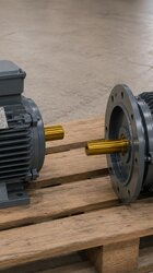
- Adapter bell housing and coupling: The motor flange is bolted to a bell housing, the pump is at the other end of the bell and the two shafts are joined by a coupling. In this arrangement a replacement can usually be made with a standard flanged motor; the spigot diameter, bolt circle and shaft length of the bell must match the new motor.
- Pump mounted directly on the motor shaft: The input of the gear pump sits on the key or slot of the motor shaft. Shaft diameter, key size and shaft extension length must match to the millimetre.
- Short or splined shaft specific to the unit: In some compact units, the motor's front end shield and shaft end are made only for that pump. In this case a standard motor cannot be fitted directly; a special motor or an intermediate adapter is needed. Such motors may fall outside the scope of the standard series in HEM Motor's 2026 catalogue; ask us with the nameplate and photos.
Whether the motor sits horizontally on the unit or vertically on top of the tank also determines the mounting arrangement. B5, B14 and vertical options are offered according to the frame, and the flange size is confirmed with the order; the mere label "B14" does not prove that it fits the existing bell housing. Compare the dimensions in the 2D technical drawings; the options are listed in the mounting arrangements question.
Direction of rotation and first start
Gear pumps are mostly unidirectional; their housings carry an arrow. If two phases are swapped on a three-phase motor, the motor runs in reverse and the pump delivers no oil, and it can be damaged if this lasts long. After the new motor is connected, the direction should be checked according to the pump manufacturer's instructions and with as short a pulse as possible. If the direction is wrong, two phases are swapped at the terminal board.
The lift's mechanical locks, lowering valve, pressure relief valve and other safety devices belong to the machine manufacturer's design. The motor replacement should be done without touching the settings of these parts; valve settings should only be changed according to the manufacturer's instructions.
Power, speed and supply are read from the nameplate
The flow delivered by the pump is proportional to motor speed. Most lift units have a 2-pole motor; if a 4-pole motor is fitted instead, the flow drops by roughly half and lifting takes longer. Raising the speed to lift faster, on the other hand, may exceed the limits of the pump and valves. The safest way is to choose the same power and rated speed as on the old motor's nameplate.
| Information to check on the old motor | Why does it matter? |
|---|---|
| Power (kW) and rated speed | The pump's flow and the torque needed at pressure were chosen for these values. |
| Phase and voltage | A single-phase workshop needs a single-phase motor, a three-phase supply a three-phase motor. |
| Duty type (S1, S2, S3) | Shows the motor's heating margin during back-to-back lifts. |
| Shaft diameter, key, flange | Decides whether the pump or bell housing will fit the new motor. |
| Pump direction of rotation | The first item to check after connection. |
On HEM Motor's three-phase models up to 3 kW, the voltage is 230/400 V (Δ/Y); these motors are connected in star on a 400 V supply. Models of 4 kW and above are 400/690 V and are connected in delta on a 400 V supply. For single-phase workshops the single-phase series covers 0.18–5.5 kW; ask us with the nameplate data for the right power. Set the thermal protection according to the rated current on the new motor's nameplate; you will find details in our motor protection article.