English
 Français
 Türkçe
 Español
 Русский

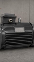
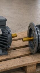
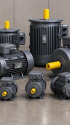
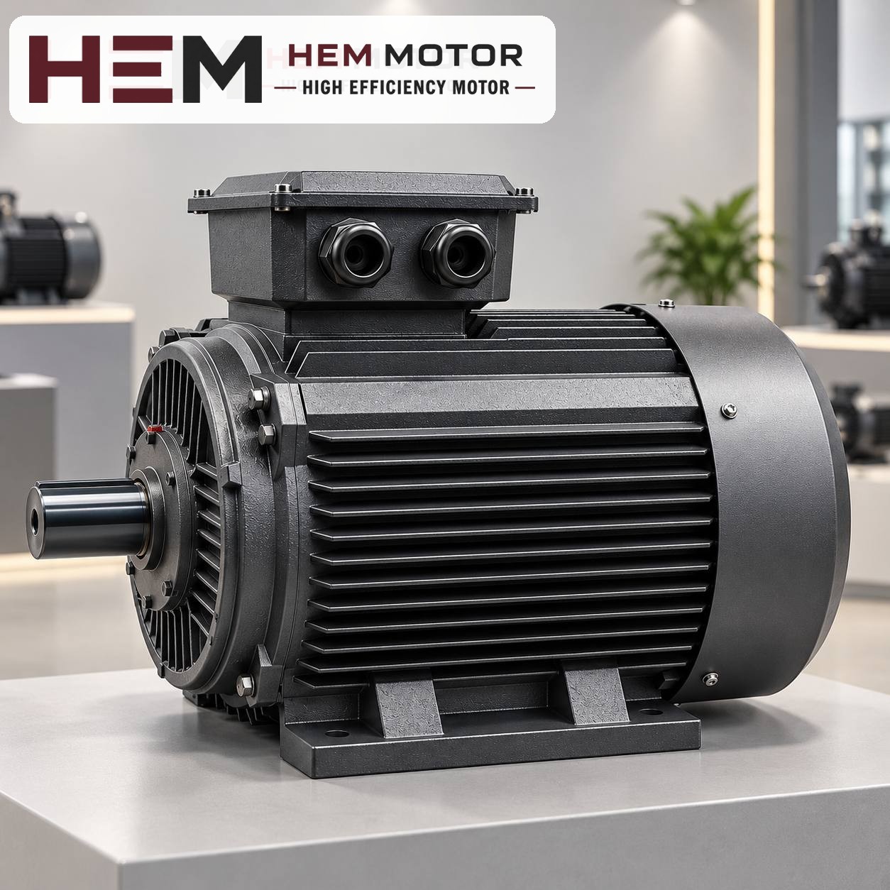

The conversation that wastes the most time in flange motor orders goes like this: someone says "we need a B5" or "we need a B14", the motor arrives, and the flange does not fit the mating part. The problem is rarely the name of the mounting arrangement; it is the dimensions behind that name. This article walks through which dimensions you should ask for, which ones you should measure on site and what you should compare them with before ordering a B5 or B14 flange motor. We do not give figures; the dimensions for each frame are in the catalogue and the technical drawings, and the aim here is to ask the right questions in the right order.

Where do B5 and B14 differ dimensionally?
In both arrangements the motor is attached to a gearbox, a pump or a machine housing through a mounting face on the front end shield. The difference is determined by where the bolt passes through:
- B5 (large flange with through holes): The outer edge of the flange usually extends beyond the frame and carries holes that go right through. The bolt passes through the flange from the motor side and is fastened into a thread or nut on the mating part. In IEC designation this type is marked "FF".
- B14 (face flange with tapped holes): The mounting face is smaller and stays within the outline of the frame. The holes are tapped blind holes; the bolt comes through the mating part and screws into the motor's front end shield. In IEC designation it is marked "FT".
This structural difference also changes how you measure. On a B5 the hole size is a clearance hole; on a B14 the hole size is a thread size and is read together with the thread pitch. In addition, more than one B14 size can be found on the market for the same frame; the distinction between a "standard" and a "large" B14 is one of the reasons why orders placed with the mounting name alone fail.
Dimensions that need to be compared
In catalogues and technical drawings, flange dimensions are given with letter codes. The list below sets out the items that should be confirmed from the old motor or the mating part before ordering:
| Dimension (code on the drawing) | What it describes | What happens if it does not match |
|---|---|---|
| Flange outer diameter (P) | The overall size of the mounting face | The flange does not fit its seat or hits surrounding parts |
| Spigot diameter (N) | The diameter of the register that centres the motor on the mating part | The shaft axis stays offset; bearings and gears are strained |
| Pitch circle diameter (M) | The diameter of the circle through the centres of the bolt holes | The holes do not line up with the holes in the mating part |
| Number of holes and hole diameter / thread size (S) | How many bolts are used and how thick they are | The bolt does not pass through or does not engage the thread |
| Spigot height (T) | How far the spigot projects from the flange face | The motor does not sit flat against the face, causing angular error |
| Shaft diameter (D) and shaft length (E) | The thickness and length of the shaft end that transmits power | The coupling, pulley or gearbox bush does not fit on the shaft or does not grip enough of it |
| Key width and key height (F, GA) | The size of the keyway on the shaft and of the key | The key does not seat in the keyway; torque transmission becomes unsafe |
If even one of these seven items is different, the motor "almost fits"; on site this means an adapter plate, a bush or a machining job. Comparing all of them in one table before ordering is much cheaper than adapting afterwards.
Points to watch when measuring on site
If the old motor's nameplate is unreadable, or the motor has been replaced before and the original is unknown, you will have to take the measurements yourself. A few practical points help:
- The pitch circle diameter is hard to measure directly. On a four-hole flange you can measure the distance between the edges of two opposite holes and add or subtract one hole diameter to arrive at the centre-to-centre distance. If the number of holes is different, evaluate the measurement together with the drawing.
- On the spigot, the motor is male and the mating part is female. Measure the motor's register from the outside and the recess on the gearbox or pump side from the inside. The two values should be very close; a difference that looks small here still creates axis misalignment.
- Verify the thread size of B14 holes with the bolt. Remove the old bolt and note its diameter and pitch. The depth of the blind hole also matters; a bolt that is too long can bottom out and fail to clamp the flange.
- Clean the shaft end before measuring. Rust, paint or coupling residue makes the diameter look larger than it is. Take the shaft length from the flange face to the end of the shaft; remove the key and measure the keyway width separately.
- Take photos. A clear photo of the flange from the front, of the shaft from the side and of the nameplate if there is one often reveals a typing error in the measurement table.