Choosing an Electric Motor When Converting a Belt and Pulley System to a Coupled Drive

Choosing an Electric Motor When Converting a Belt and Pulley System to a Coupled Drive

On many machines that have run for years, the belt-and-pulley arrangement is questioned because of its maintenance burden: the belt stretches, needs re-tensioning, the pulley grooves wear and belt dust contaminates the surroundings. Connecting the motor directly to the machine shaft with a coupling comes to mind as the solution. This change is possible, but if it is made without changing the motor it often ends with the wrong speed. In this article we explain in which order to deal with motor speed, frame, shaft height and alignment when converting from a belt drive to a coupled drive.
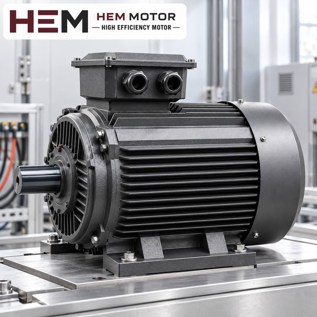
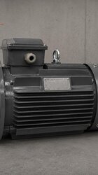
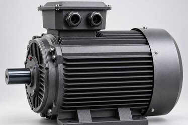
Three-phase electric motor on a test bench
In a coupled drive the motor shaft and the machine shaft must meet on the same axis (representative image).

What happens to speed when the pulley ratio disappears?

In a belt drive, the machine's rotational speed is found by multiplying the motor speed by the ratio of the pulley diameters. If there is a small pulley on the motor side and a large one on the machine side, the machine turns slower than the motor; in the opposite case it turns faster. In a large share of belt systems, this ratio was chosen precisely to bridge the gap between standard motor speeds and the speed the machine needs.

A coupling, however, does not change speed. The motor shaft and the machine shaft rotate at exactly the same speed. So the first question when moving from a belt to a coupled drive is: Is the speed at which the machine shaft turns today close to the rated speed of a standard motor?

  • If the pulleys are the same diameter (ratio 1:1): The machine is already turning at motor speed. You can switch to a coupled arrangement while keeping the existing motor's number of poles; the main job is the mechanical layout and alignment.
  • If the ratio is clearly different from 1:1: With the same motor, a coupled connection changes the machine's speed. If the machine speed corresponds to a different number of poles (e.g. 1,000 instead of 1,500 rpm), the motor changes; if it does not match any standard speed, a gearbox or a frequency inverter is considered.

How do you find the machine speed?

The most reliable way is to measure the speed of the machine shaft while running with a tachometer. If no measurement is possible, you get an approximate value by multiplying the rated speed on the motor nameplate by the motor pulley diameter and dividing by the machine pulley diameter. The result is more accurate if the effective diameter inside the groove is used as the pulley diameter; the outer diameter can be slightly misleading. Also allow for belt slip reducing the speed somewhat.

If speed changes, frame and torque change too

At the same power, a lower-speed motor delivers higher torque to the shaft, and this usually requires a larger frame. Two 7.5 kW models from the HEM Motor range show this:

ModelPoles / rated speedIEC frameRated torqueVoltage
132M-4 cast iron4 poles / 1,460 rpm132M49.1 Nm400/690 V (Δ/Y), 50 Hz
160M-6 cast iron6 poles / 970 rpm160M73.8 Nm400/690 V (Δ/Y), 50 Hz

On a machine that a belt brings down from a 1,460 rpm motor to about 970 rpm, the torque reaching the machine shaft in the belt arrangement has also been increased by the pulley ratio. When you switch to a coupling, this torque increase must now be provided by the motor itself; the higher rated torque of the 6-pole motor is therefore a necessity. Because the frame grows from 132M to 160M, the base also changes. For the frame–power relationship see the IEC frame–power table, and for torque values the torque table.

Do not base the power choice on the old motor's nameplate alone. A belt arrangement has belt losses; a coupled arrangement does not. This difference is usually small, however; what really decides is the machine's load, starting condition and duty.

Mechanical layout: base, shaft height and shaft end

In a belt arrangement the motor is usually placed beside or below the machine on tensioning rails or a hinged base. In a coupled arrangement the motor shaft has to come onto the same axis as the machine shaft. This changes the layout from the start:

  • Shaft height: The number in the IEC frame code describes the height of the motor shaft above the foot base. If the machine shaft height is different, a precisely machined base or shims are needed under the motor.
  • Base rigidity: A tensioning rail does not provide a sufficiently stable foundation in a coupled arrangement. Bringing the motor and machine together on a common, rigid baseframe makes it easier to keep the alignment.
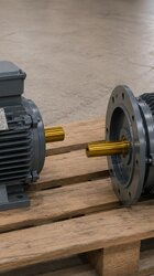
  • Shaft end and coupling hub: The bore and keyway of the coupling hub must suit the motor shaft. Check whether a shaft length that was enough for a pulley is also suitable for the coupling hub.
  • Mounting arrangement: In coupled drives the most common arrangement is the B3 foot-mounted motor. If the motor is to be connected to the machine through an intermediate flange, a flange option is discussed. Mounting arrangements are offered according to the frame and the flange size is confirmed with the order.

Shaft diameter, shaft length, shaft height and foot hole spacing are given per frame in the technical and product catalogue and the 2D technical drawings. Design the base according to these drawings.


Prices and technical data are on the product pages; choose a model and order online.

Alignment: the real work of a coupled drive

A belt tolerates small alignment errors to some extent. A coupling, however, locks the motor and machine shafts together and passes the error straight on to the bearings. Flexible couplings absorb some misalignment, but this tolerance is no excuse for skipping alignment.

  • Parallel misalignment: The two shafts are parallel but their axes are offset up-down or left-right. It is usually corrected with shims and lateral jacking bolts.
  • Angular misalignment: The shaft axes are at an angle to each other. It shows up as a gap between the coupling faces that is not equal around the circumference.
  • Soft foot: If one of the motor feet does not bear fully on the base, the frame flexes when the bolt is tightened and the alignment is lost. Each foot is checked separately before alignment.
  • Coupling gap: The gap between faces specified by the coupling manufacturer is kept; axial movement of the motor must not compress the coupling.

Alignment is done with a straightedge and feeler gauges in simple applications, and with dial indicators or a laser alignment tool for precise work. The values allowed by the coupling manufacturer apply. After the first run, it is good practice to recheck the alignment once the motor and machine have reached operating temperature. For the first energising steps see our commissioning article.

Example: converting a belt-driven mixer to a coupled drive (hypothetical)

The sequence below is a hypothetical example constructed for illustration; it is not a real customer application. Suppose a mixer runs with a 7.5 kW, 1,460 rpm motor through a belt and pulleys. The measured machine shaft speed is about 970 rpm.

  • Calculate the ratio: 1,460 / 970 ≈ 1.5. In a coupled arrangement the same 4-pole motor would speed the machine up by about 1.5 times.
  • Determine the number of poles: The target speed is close to the rated speed of a 6-pole motor. In the HEM Motor range, the 160M-6 cast iron model for 7.5 kW has a rated speed of 970 rpm.
  • Reassess the load: Whether the power will still be 7.5 kW is checked together with the mixer's load, product density and starting condition. In this example the power is assumed not to change.
  • Redesign the base: Because the frame is 160M, the shaft height and foot holes differ from the old 132M motor. The common baseframe is prepared from the technical drawing according to the machine shaft height.
  • Align and check: Soft foot is eliminated, parallel and angular misalignment are brought within the coupling values, and a hot alignment check is made after the first run.

Other example models in a similar power range

  • 160M-4 cast iron: 11 kW (15 HP), 4 poles, 1,465 rpm, IEC 160M, 400/690 V (Δ/Y), 50 Hz, IP55, insulation class F.
  • 160L-6 cast iron: 11 kW (15 HP), 6 poles, 970 rpm, IEC 160L, 400/690 V (Δ/Y), 50 Hz, IP55, insulation class F.

At 11 kW the 4-pole and 6-pole models both have a 160 shaft height, but 160M and 160L differ in foot spacing and frame length. Current prices are on the product pages.

Information to send us when converting to a coupled drive

  • A photo of the existing motor's nameplate (power, speed, frame, voltage)
  • The diameters of the motor and machine pulleys, or the measured machine shaft speed
  • The type of machine, load characteristics, starting condition and daily operating time
  • The height and diameter of the machine shaft and the coupling type to be used
  • Mounting arrangement (B3, flange or B35) and the condition of the base
  • Supply voltage and starting method

Review suitable models and current prices on the buy electric motors page. If you write to us with the pulley details and the motor nameplate via the nameplate submission page or our contact page, we can determine together the speed and model suited to the coupled arrangement.

HEM Motor Models Related to This Article

The cards show example models related to the topic. A suitable motor is not chosen by power alone: compare speed, voltage, mounting, shaft and connection dimensions on the product page; if unsure, send a photo of the existing motor’s nameplate on WhatsApp.

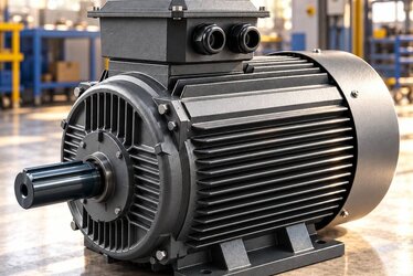
7.5 kW 1500 rpm Cast Iron Frame Electric Motor 132M-4

132M-4

7.5 kW · 1500 rpm

  • Cast iron frame · IEC 132M
  • 1460 rpm · IP55
  • Mounting: B3 foot; flange (B5/B14/B35) depending on frame — confirmed with the order

US$392.38 (€350.17)

View product
7.5 kW 1000 rpm Cast Iron Frame Electric Motor 160M-6

160M-6

7.5 kW · 1000 rpm

  • Cast iron frame · IEC 160M
  • 970 rpm · IP55
  • Mounting: B3 foot; flange (B5/B14/B35) depending on frame — confirmed with the order

US$575.79 (€513.85)

View product
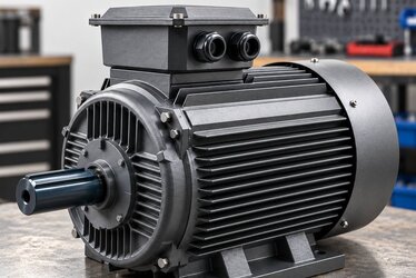
11 kW 1500 rpm Cast Iron Frame Electric Motor 160M-4

160M-4

11 kW · 1500 rpm

  • Cast iron frame · IEC 160M
  • 1465 rpm · IP55
  • Mounting: B3 foot; flange (B5/B14/B35) depending on frame — confirmed with the order

US$565.14 (€504.35)

View product

Similar Articles