English
 Français
 Türkçe
 Español
 Русский

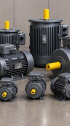
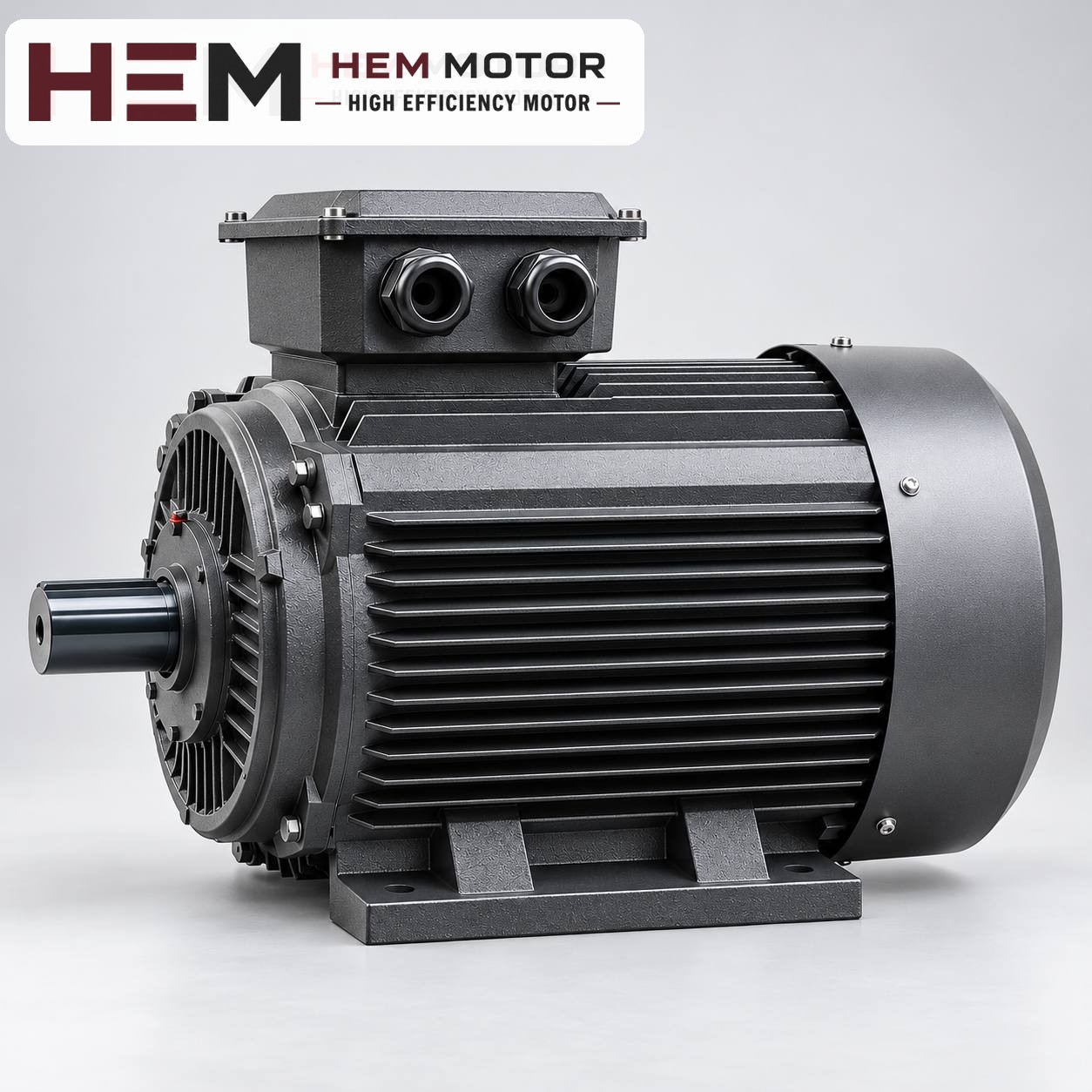

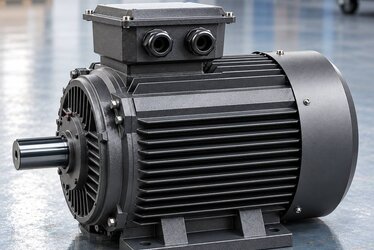
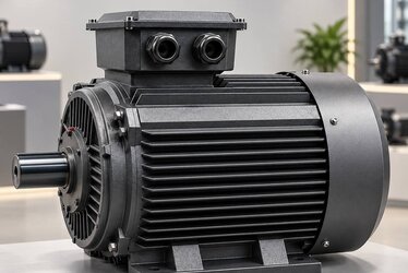
When replacing a motor in a tight installation space, the same IEC frame code alone is not a sufficient guarantee. The frame code defines shaft height, foot hole spacing and shaft end; the motor's overall length, the rearward projection of the fan cover, and the height and position of the terminal box may vary from one manufacturer to another. That is why, before replacement, you need to look not at the motor's feet but at the clearances around it.
This article deals with replacing motors that are built into a machine body, stand close to a wall or other equipment, or are fitted into a covered compartment. The aim is for the new motor not only to fit in place but also to be able to cool while running and to be maintained.

What does the IEC frame code fix, and what does it not?
The IEC standard harmonises the dimensions by which motors of the same frame code connect to the machine. So a motor with a 132M frame can be replaced by another 132M motor that sits on the same base at the same coupling alignment. However, the standard does not limit the motor's external dimensions outside the connection.
| Dimension | Fixed by the frame code? | Effect in a tight space |
|---|---|---|
| Shaft height (from foot base to shaft axis) | Yes | Coupling and pulley alignment is maintained. |
| Foot hole spacing (lengthwise and crosswise) | Yes, according to the letter (S, M, L) | It bolts to the base using the same holes. |
| Shaft end diameter and length | Yes, according to frame and number of poles | The coupling or pulley hub fits. |
| Overall motor length | No | It may hit the rear wall or a cover. |
| Fan cover diameter and projection | No | The clearance left for air intake may narrow. |
| Terminal box height and position | No | It may hit the panel above; cable direction may change. |
You can see how frame codes relate to power in our electric motor frame size table article. The dimension values for each model are in the 2D technical drawings and the 2026 technical and product catalogue; we give no dimension figures in this article, because the comparison should be made on the drawing.
Clearances to measure on site
Before the old motor is removed, measure and photograph the clearances around it. Once it has been removed, these measurements are hard to reconstruct.
- Rear clearance: The distance between the rearmost point of the fan cover and the wall, panel or other equipment. The motor draws air from here.
- Top clearance: The distance between the top of the terminal box cover and the ceiling, cover or part above. The cover must open and the cable must be able to bend.
- Side clearances: The distance between the frame fins and the side walls; room is also needed for the lifting eye and installation tools.
- Cable route: The direction from which the cable enters the terminal box, which side the gland is on and how much slack the cable leaves.
- Shaft side: The clearance between the coupling or pulley guard and the motor's front end shield; needed so that the motor can be slid back and forth during replacement.
Sending these measurements together with the old motor's nameplate when ordering is the quickest way.
Terminal box: position, orientation and cable slack
The most common problem in a tight space is the terminal box hitting a panel or machine cover. The new motor's terminal box may be taller, or the cable entry may face a different direction. In that case there are three options:
- On designs where the terminal box can be rotated, the cable entry direction can be changed; ask in the order whether this is possible for the model and frame.
- The position of the terminal box (top or side) is an order item; if a position different from the standard design is needed, state it clearly.
- If the cable slack is not enough, rearrange the cable route instead of forcing the cable to bend; a sharp bend and a stretched cable lead to moisture ingress at the gland and loosening.
Another detail is the voltage change. Models up to 3 kW are rated 230/400 V, and models of 4 kW and above are rated 400/690 V. If the old motor had a different voltage rating, the terminal links and panel connection also change; in a tight box, the cover must open fully for this work to be possible.
Cooling clearance: do not block the front of the fan cover
A standard three-phase motor draws air from the surroundings with the fan at its rear and blows it along the frame fins. If there is a wall right behind the fan cover, the motor re-draws its own hot air; the frame heats up and winding and bearing life shorten. This is common in tight spaces and is often mistaken for a lack of power.
- Leave a clearance between the fan cover and the obstacle behind it that allows air to flow; for the recommended distance, use the technical drawing and catalogue notes as the basis.
- For a motor working in a closed compartment, the compartment itself must be ventilated; if the motor keeps re-drawing the air it has heated, the ambient temperature rises.
- Measure the air temperature inside the compartment and state it in the order.
For more on cooling methods, see our IC411/IC416 cooling methods article.
You can compare models of suitable frame and power and their current prices on the buy electric motors page.