English
 Français
 Türkçe
 Español
 Русский

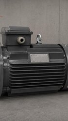
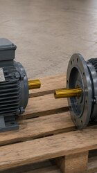
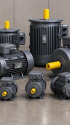
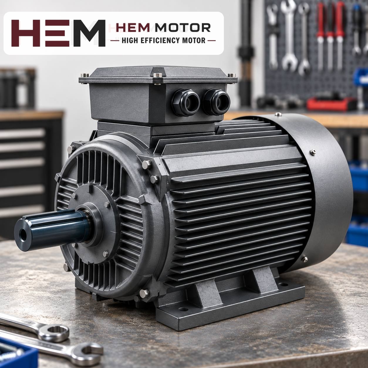

When the motor of a press brake's hydraulic unit is replaced, flange and coupling compatibility is checked at three points: the new motor's flange must seat in the spigot recess and bolt holes of the existing pump bell housing, the shaft diameter and key must fit the coupling hub, and the shaft length must bring the coupling halves together at the correct axial gap. If any of these three does not match, the bell housing, coupling or an adapter flange changes. This article explains how these checks are carried out on site for layouts typical of press brake units, how to assess the flexible coupling and when a standard motor cannot take the old one's place.
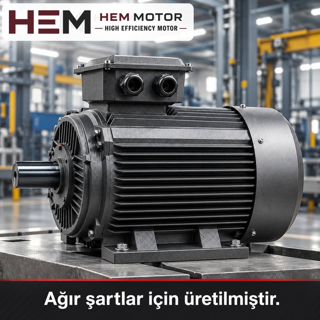
How is the motor arranged on press brake units?
On press brakes, the hydraulic unit is usually on a tank placed on the side frame or at the back of the machine. Three layouts are most common on site:
- Vertical on top of the tank (V1, shaft down): The motor stands upright on the tank lid; the pump hangs into the oil below the lid together with the bell housing. It is common because it is compact and quiet. The motor flange carries the weight of both the pump and the bell housing.
- Horizontal on top of the tank (B35 or B5): The motor is horizontal; the bell housing and pump are attached to the flange. With a foot-and-flange motor, the feet transfer the load to the base.
- Oil-immersed motor-pump unit: In some compact units the motor is also in the oil. The motor in this design is a special motor built for operation immersed in oil.
Oil-immersed motors and pump systems driven by servo motors may fall outside the scope of the standard series in HEM Motor's 2026 catalogue; for such units, ask us with the nameplate and application details. The checks below apply to conventional units in which the motor stands outside the tank and runs at fixed speed.
Flange compatibility: what information is taken from the old motor?
The name of the flange alone is not enough. Two "B5 flange" motors may have different flange sizes. Before the old motor is removed, record the following:
- Flange type: If the holes in the flange go right through (the bolt passes through from behind the flange), it is the large flange, corresponding to the B5 arrangement. If the holes are threaded (the bolt is screwed in from the bell housing side), it is the small flange, corresponding to the B14 arrangement. Both are found on press brake units.
- Spigot diameter: The diameter of the raised part of the flange that fits into the bell housing. Because the bell housing is centred on this diameter, the dimension must be exactly the same.
- Pitch circle and number of holes: The diameter of the circle passing through the centres of the bolt holes, and the number of holes.
- Nameplate information: The IEC frame code (e.g. 132M) and, if present, the flange code. If the nameplate does not show a flange code, the measurement is the reference.
Mounting arrangements are offered according to the frame; the flange size is confirmed with the order. Sending the values above in writing with the order therefore eliminates the risk of a motor arriving with the wrong flange. Flange and shaft dimensions by frame are given in the 2D technical drawings and the 2026 technical catalogue; the mounting options are summarised in the question on mounting arrangements.
Coupling compatibility: before reusing the flexible coupling
On press brake units, the motor and pump are usually connected by a jaw coupling with two metal hubs and a flexible insert between them (commonly called a "spider" or "star"). When replacing the motor, the coupling is assessed in three respects:
- Motor-side hub: The hub's bore and keyway must fit the new motor's shaft. With a new motor of the same frame code this is usually the case; if the frame changes, a new hub is needed. The hub is not hammered onto the shaft; it is fitted by heating or with a puller.
- Flexible insert: A hardened, cracked or crushed insert increases vibration and noise. Replacing the motor is the right moment to renew the insert. The material and hardness of the insert are selected according to the coupling manufacturer's table.
- Hub position: The axial gap specified by the coupling manufacturer must be left between the two hubs. If the hubs butt against each other, axial load acts on the pump shaft bearing; if they are too far apart, the jaws do not engage sufficiently.
Shaft length and bell housing depth: an often-skipped check
If the new motor's shaft length differs from the old one, the point where the two hubs meet inside the bell housing shifts, even if the motor hub is fitted at its old position on the shaft. A practical way to check this on site is:
- Before removing the old motor, measure the depth from the bell housing flange face to the front face of the pump hub.
- On the old motor, note the length from the flange face to the shaft end and the position of the hub on the shaft.
- Take the same measurements on the new motor; fix the hub at a position that leaves the gap specified by the coupling manufacturer between the two hubs.
- On a vertical unit, the hub's set screw or key must be tightened before the motor is lowered into place; otherwise the hub can slide on the shaft.
If the new motor has a different frame code (e.g. moving from 132 to 160 because of higher power), the bell housing does not fit directly. In that case either a new bell housing or an adapter flange between motor and bell housing is needed; because the adapter flange also changes the shaft length, the coupling hub position is recalculated.