Buying a 110 kW Electric Motor: Matching Speed and Drive System

Buying a 110 kW Electric Motor: Matching Speed and Drive System

When buying a motor in the 110 kW class, choosing the speed is a decision about the driven system more than about the motor itself. At the same power, 1,000, 1,500 and 3,000 rpm models deliver very different torques to the shaft, which raises the question of whether the coupling, the belts, the gearbox and the machine shaft can carry that torque. In this article we use HEM Motor's three 110 kW models as examples to explain how to match motor speed to the drive system and which transmission elements to check before ordering.
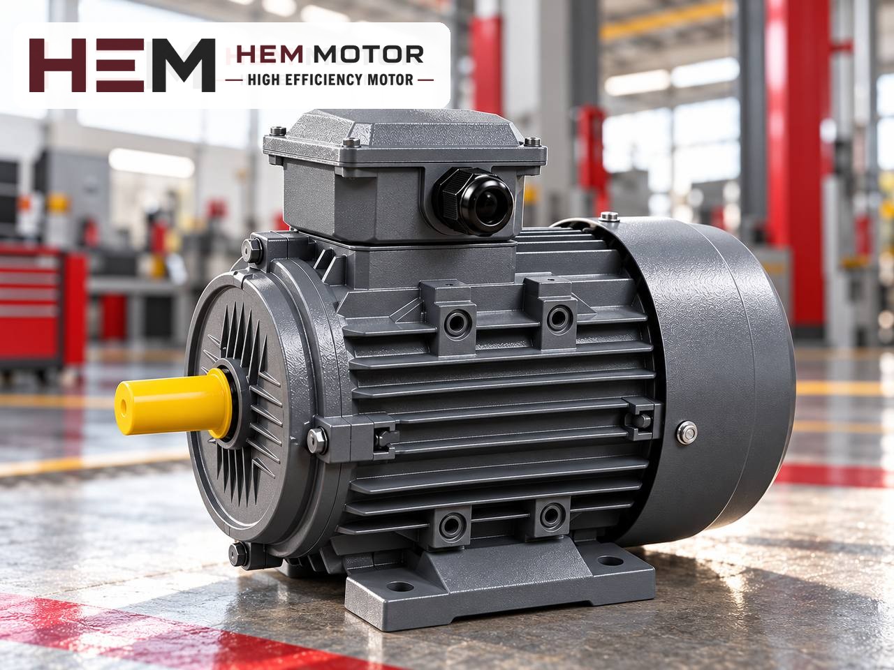
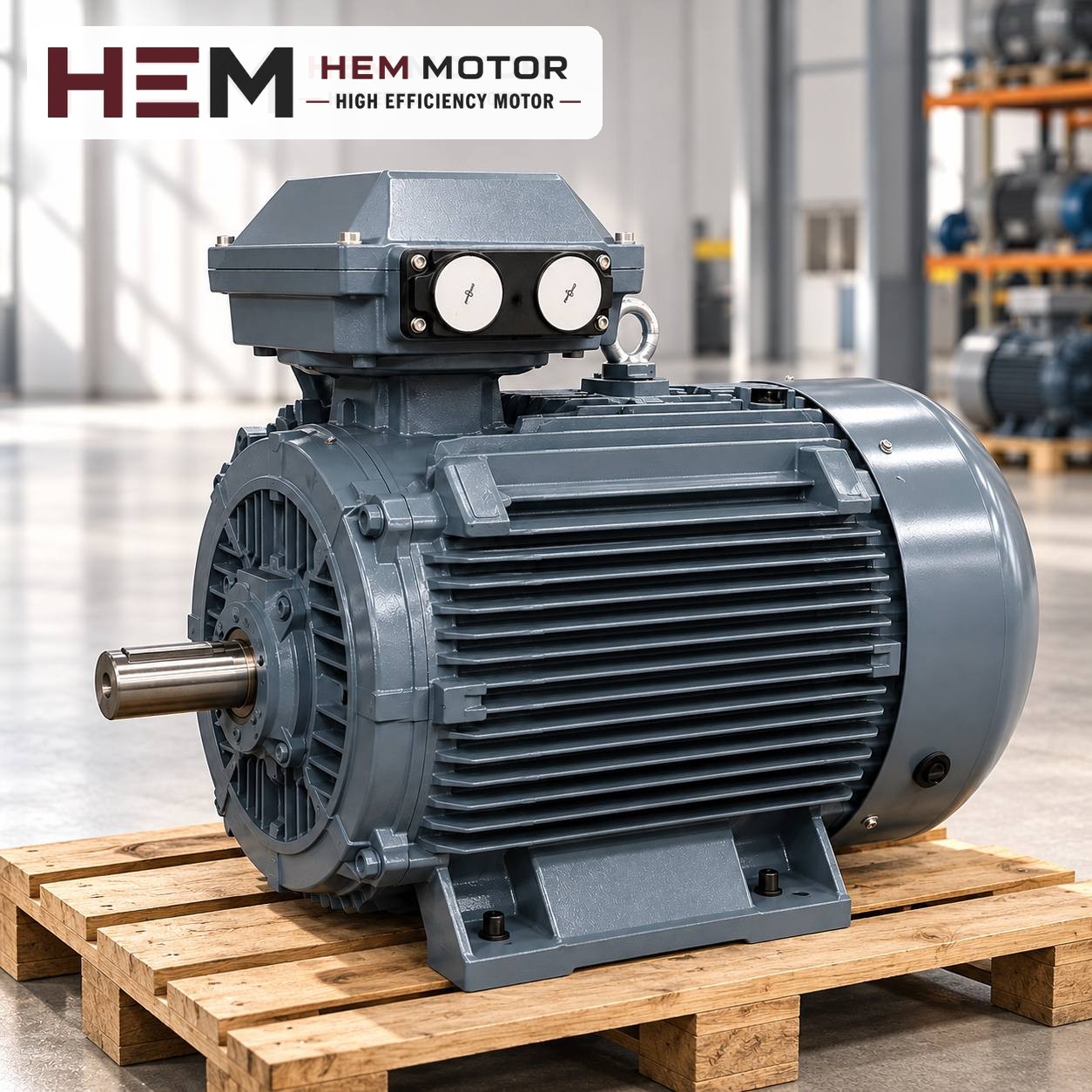
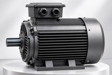
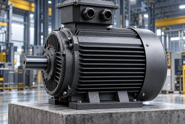
High-power cast iron three-phase motor standing on a workshop floor
At high power, the choice of speed affects the whole transmission chain from the motor shaft to the machine (representative image).

110 kW models: same power, three different torques

HEM Motor's 110 kW options have cast iron frames and come in three speeds. The degree of protection is IP55 and the insulation class F; the supply is 400/690 V (Δ/Y), 50 Hz. As with all models of 75 kW and above, the service factor is 1.15.

CodeSpeed (synchronous / nameplate)Frame (IEC)Current, 400 VTorque (rated)
315L1-61,000 / 988 rpm315L196 A1,063 Nm
315S-41,500 / 1,488 rpm315S187 A706 Nm
315S-23,000 / 2,978 rpm315S185 A352.8 Nm

The currents are close to each other, but the torques differ by up to a factor of three. The 1,063 Nm on the shaft of the 1,000 rpm model is about three times the 352.8 Nm of the 3,000 rpm model. Every element connected to the shaft is sized for this torque, not for the motor's power. That is why there is no such thing as a "110 kW coupling" or a "110 kW belt"; the selection is made by torque and speed.

The speed the machine needs determines the motor speed

The correct motor speed is worked out backwards from the machine's operating speed and the transmission ratio in between. The order is:

  • Machine shaft speed: The speed at which the fan, pump, crusher rotor, mill or drum has to run. This value comes from the machine manufacturer or the existing arrangement.
  • Transmission type and ratio: Direct coupling (ratio 1), belt and pulley (ratio of pulley diameters) or gearbox (gearbox ratio).
  • Motor speed: The product of the machine speed and the transmission ratio. If the result falls around 985–990, 1,485–1,490 or 2,975–2,980 rpm, the corresponding number of poles is the natural choice.

If the calculation falls between two speeds, there are two routes: change the transmission ratio (pulley or gearbox) or drive the motor with a frequency inverter. Which route is suitable depends on the machine's speed range and the capacity of the transmission elements.

Checklist by drive type

Direct coupled drive

The motor speed equals the machine speed, so there is no flexibility in choosing the speed. A 2-pole pump needs 3,000 rpm and a 4-pole fan 1,500 rpm.

  • The coupling's torque capacity must cover the motor's rated torque with a suitable factor for starting and shock loads.
  • The coupling hub must fit the new motor's shaft end. In the 315S frame, 2-pole and 4-pole motors may have different shaft ends; check the dimension in the 2026 catalogue.
  • At 3,000 rpm, the coupling's maximum permissible speed and balance quality become particularly important.

Belt and pulley drive

Because the machine speed can be adjusted with the pulley ratio, there is flexibility in motor speed; but that flexibility is not free.

  • At the same power, a lower-speed motor delivers more torque; if it is to be transmitted by the same belt drive, the number of belts or the profile grows.
  • With a higher-speed motor the belt speed rises; the speed limits allowed by the pulley diameter and belt type must be checked.
  • Belt tension places a radial load on the motor shaft and the drive-end bearing. At 110 kW a small-diameter pulley increases this load; the pulley diameter and its distance from the shaft end should be assessed in the machine design. If there is a heavy radial load, state it in the order.

Gearbox drive

  • The gearbox input speed must match the motor speed; most industrial gearboxes are catalogued for a 1,500 rpm input. Driving one with a 3,000 rpm motor may exceed its permitted input speed.
  • The gearbox's thermal capacity must be checked as well as its mechanical capacity; in continuous operation a gearbox can reach its thermal limit before its mechanical one.
  • If the motor is to be flange-mounted to the gearbox, the flange size is confirmed with the order. Mounting arrangements are offered according to the frame; details are in the question on mounting arrangements.
Prices and technical data are on the product pages; choose a model and order online.

Side effects of changing speed

If you are thinking of changing the motor speed in an existing system, take the following consequences into account:

  • The machine speed changes: If the transmission ratio stays the same, the machine speeds up or slows down in the same proportion. In fans and pumps, flow changes with speed, pressure with the square of speed and absorbed power with the cube of speed. A fan moved from 1,500 to 3,000 rpm may, with the same impeller, demand power far above 110 kW.
  • The frame and base may change: In the table, the 1,000 rpm model is in a 315L frame and the others in 315S. Moving from 1,500 to 1,000 rpm changes the foot hole spacing even at the same shaft height.
  • Transmission elements are reselected: At low speed the higher torque strains the coupling, belts and gearbox input shaft; at high speed, balance and speed limits come to the fore.

Is a frequency inverter a solution?

If the machine needs to run at different speeds, a drive can make sense. In terms of speed control, our three-phase series can be used with a frequency inverter. If the motor is to remain at low speed and full torque for long periods, an external fan may be needed; if the cable between the drive and the motor is long, a dv/dt or sine filter is considered. Write these conditions in your order; details are explained in the question on use with an inverter. Running above rated frequency with a drive reduces the motor's torque and pushes mechanical limits; for that reason a drive should not be seen as a permanent fix for a wrongly chosen speed.

How does SF 1.15 affect the choice of speed?

The 110 kW models have a service factor of 1.15; the motor has a reserve able to cover about 15% more than the power written on the nameplate. This reserve provides a safety margin when the system's real load turns out slightly higher than calculated or ambient conditions become harsher. It should not be used to cover a load increased by a speed change or to choose a motor smaller than needed. Select the transmission elements, too, according to the real load and torque values with their own safety factors, not according to power multiplied by the SF.

Example scenario: renewing the motor of a belt-driven mill

The situation in this section is fictional and does not belong to a specific customer. Suppose that at a mineral grinding plant a mill runs through a belt and pulley drive with a 110 kW, 1,500 rpm motor, and the motor is to be renewed.

  • If the machine speed and pulley ratio will not change, the candidate is the 110 kW motor with model code 315S-4; its nameplate shows 1,488 rpm.
  • If the operator mentions that the belts are replaced often, the problem may lie not in the motor speed but in the number of belts, the profile or the tension; that is a mechanical review separate from the motor order.
  • If using the 315L1-6 (988 rpm, 1,063 Nm) with a larger motor pulley is considered, the belts must carry the higher torque, the new pulley ratio must be calculated, and the base and motor slide rails must be adapted for the 315L frame.
  • If the same plant has a directly coupled high-speed process pump, the 315S-2 (2,978 rpm) is considered for it; the coupling's speed limit and the pump's 2-pole design are confirmed.

Information to send for the order

  • Power and required motor speed; the machine's operating speed
  • Drive type (coupling, belt and pulley, gearbox), transmission ratio and pulley diameters if any
  • If a gearbox is used, its input speed and connection type; for a flange connection, the flange size
  • Mounting arrangement, voltage, starting method and whether a frequency inverter will be used
  • Application, operating time and, if replacing, a nameplate image of the motor to be removed

You can find 110 kW and other power ratings with current prices on the buy electric motors page, and see all high-power options in the cast iron frame motors list. If you are replacing an old motor, send the nameplate photo via the equivalent finder page; we will settle the right speed together with your drive details. For other questions you can use our contact page.

HEM Motor Models Related to This Article

The cards show example models related to the topic. A suitable motor is not chosen by power alone: compare speed, voltage, mounting, shaft and connection dimensions on the product page; if unsure, send a photo of the existing motor’s nameplate on WhatsApp.

110 kW 1500 rpm Cast Iron Frame Electric Motor 315S-4

315S-4

110 kW · 1500 rpm

  • Cast iron frame · IEC 315S
  • 1488 rpm · IP55
  • Mounting: B3 foot; flange (B5/B14/B35) depending on frame — confirmed with the order

US$4,832.00 (€4,312.23)

View product
110 kW 3000 rpm Cast Iron Frame Electric Motor 315S-2

315S-2

110 kW · 3000 rpm

  • Cast iron frame · IEC 315S
  • 2978 rpm · IP55
  • Mounting: B3 foot; flange (B5/B14/B35) depending on frame — confirmed with the order

US$4,953.07 (€4,420.27)

View product
110 kW 1000 rpm Cast Iron Frame Electric Motor 315L1-6

315L1-6

110 kW · 1000 rpm

  • Cast iron frame · IEC 315L
  • 988 rpm · IP55
  • Mounting: B3 foot; flange (B5/B14/B35) depending on frame — confirmed with the order

US$5,089.53 (€4,542.06)

View product

Similar Articles