English
 Français
 Türkçe
 Español
 Русский

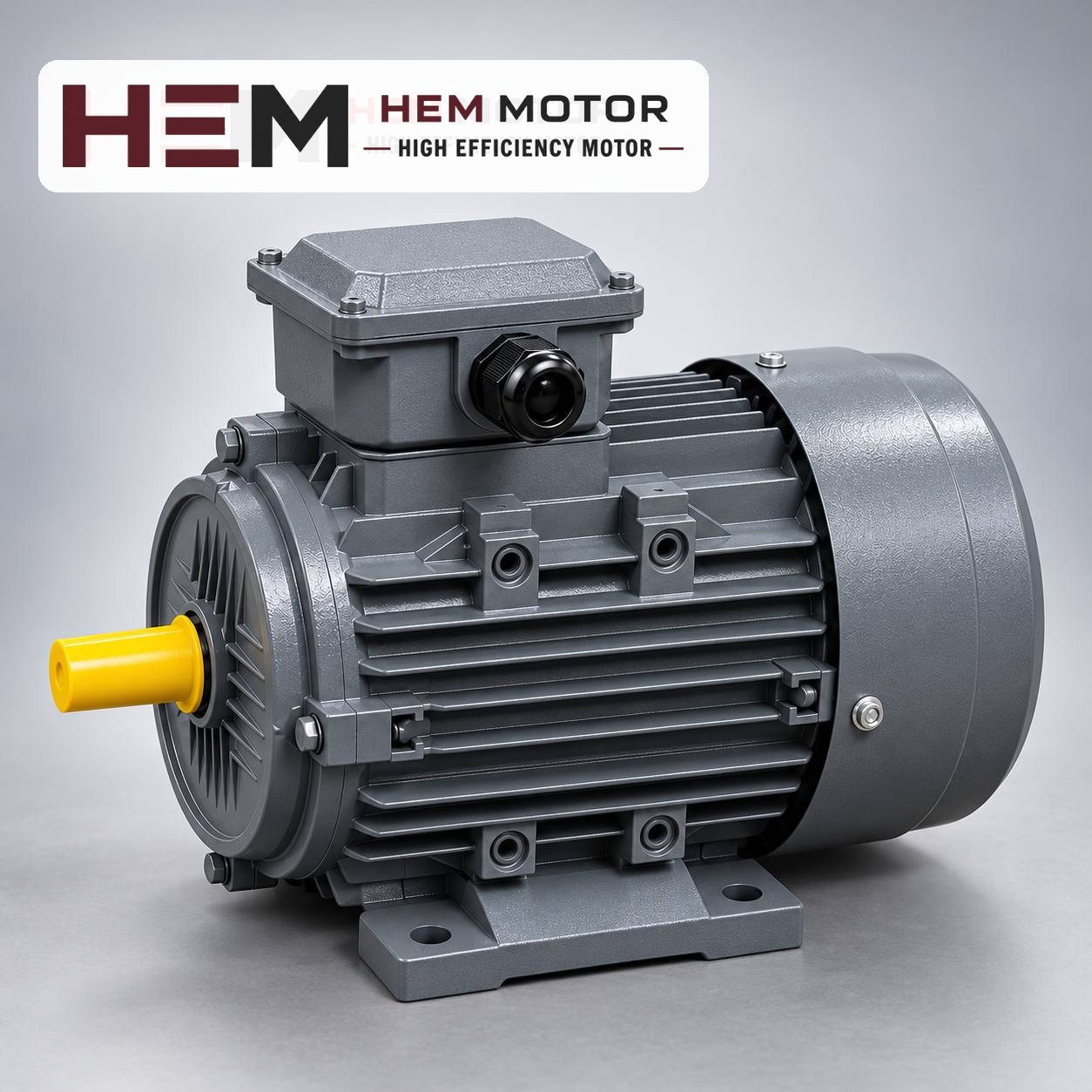

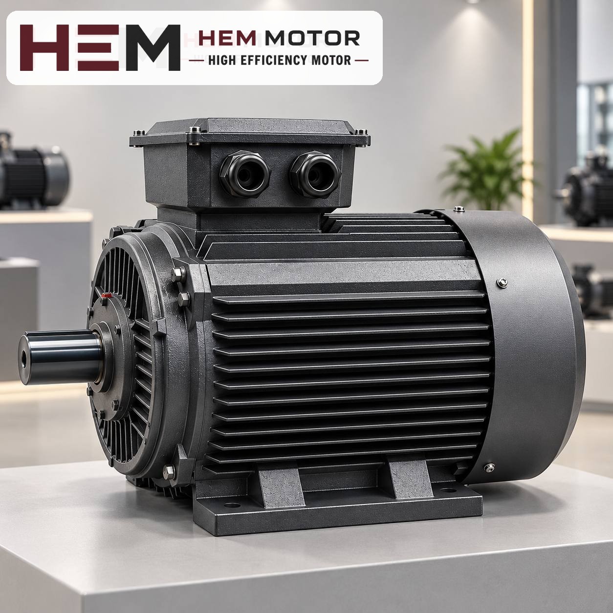
When replacing the motor of a plastic extruder, the first value to look at is not power but the torque required by the screw shaft. An extruder screw is a constant-torque load that requires roughly the same torque even when speed falls; the new motor must therefore be able to deliver continuously the torque needed at the lowest and highest screw speeds the machine runs at, and be able to cool within this range together with the inverter. When replacing an old DC motor with a three-phase induction motor and a frequency inverter, these two conditions are more important than matching the power rating.
What does an extruder screw require from the motor?
In an extruder, the screw conveys granules through a heated barrel, compresses them and pushes the melt into the die. The friction on the screw surface and the resistance of the melt create a torque requirement that is largely independent of speed. Roughly speaking: when the screw turns at half speed, the required torque stays about the same while the power consumed halves. This is completely different from pumps and fans, whose load falls quickly with speed.
The main factors that change the torque requirement are:
- Material and melt viscosity: Different polymers on the same machine require different torque. If the barrel temperature is kept low, the melt thickens and torque increases.
- Die and screen resistance: A screen pack that is starting to clog raises back pressure and therefore torque.
- Cold start: If the screw is turned before the barrel has warmed up sufficiently, torque rises sharply. This is a process error; upsizing the motor is not the solution.
Torque comparison before replacement
The rated torque at the motor shaft is calculated from power and speed: torque (Nm) ≈ 9,550 × power (kW) / speed (rpm). Find this value from the old motor's nameplate and compare it with the rated torque of the new motor. Two motors with the same power but different speeds have different torque; in an extruder, torque is what must be compared.
Switching from a DC motor to an AC motor
The nameplate of DC motors, often found on older extruders, usually shows a "base speed"; the motor runs at constant torque up to this speed. The base speed of the DC motor may differ from the rated speed of a 4-pole induction motor. In this case there are two routes:
- If the same shaft speed is targeted: The new motor's rated torque must not be lower than the old motor's torque at base speed. The speed at the gearbox input is maintained.
- If the speed is different: The screw speed is maintained by adapting the pulley ratio or the gearbox input; in this case the torque required at the shaft is also recalculated with the ratio.
DC motors are often built with special flange and shaft dimensions. Since the connection of an IEC-frame induction motor may differ, adaptation of the base, coupling or pulley may be required. For dimensions see the 2D technical drawings by frame; mounting arrangements are offered according to the frame and the flange size is confirmed with the order.
Inverter compatibility: speed range and cooling
Because the screw speed of an extruder is adjusted to the process, the induction motor almost always runs on a frequency inverter. HEM Motor's three-phase series are suitable for speed control with a frequency inverter; for long periods at low speed with full torque an external fan may be required, and if the cable between the inverter and the motor is long, a dv/dt or sine filter is considered. These conditions must be stated with the order. For general information see the question on inverter operation.
- Below 50 Hz: The motor can deliver its rated torque, but cooling decreases because the shaft-mounted fan also slows down. If the extruder runs for long periods at low screw speed and high torque, this is why the motor heats up; an external (independent) fan meets this need.
- Above 50 Hz: Because voltage stays constant, the motor enters the field-weakening range; power remains roughly constant while usable torque falls. With a constant-torque extruder load, raising the frequency to increase screw speed can lead to insufficient torque.
- Control precision: Speed stability and response to load changes depend on the type and setting of the inverter. If line precision requirements are high, select the inverter together with the inverter supplier; the standard motor does not determine this performance on its own.
When the motor is first run on the inverter, the nameplate values (voltage, current, speed, frequency) must be entered correctly into the inverter. For commissioning steps, see our first start-up check article.
Gearbox and coupling side
An extruder gearbox has a thrust bearing that carries the axial force generated backwards by the screw. This force is not transmitted to the motor, but the gearbox's input speed and torque capacity must be compatible with the motor. If the motor is connected to the gearbox by belt and pulley, the pulley ratio determines the screw speed; if it is connected directly with a coupling, shaft height and alignment are checked. The new motor's torque must not exceed the gearbox's input torque limit; if power is to be increased, the gearbox data are examined separately.