English
 Français
 Türkçe
 Español
 Русский

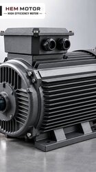
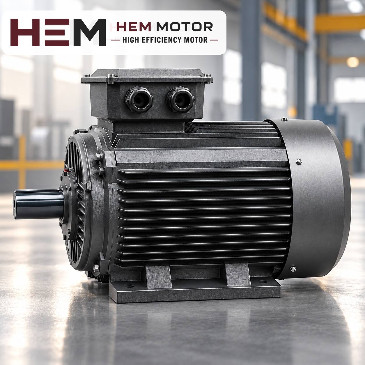

In biological wastewater treatment plants, the blower that pushes air into the aeration basin is considered the heart of the plant. If the bacteria run out of oxygen the treatment process breaks down; that is why the blower motor runs non-stop for weeks or even months. The points to check when choosing a motor or replacing a failed one are somewhat different from those of an ordinary machine motor: load type, continuous operation, outdoor conditions and acoustic enclosure conditions are assessed together. In this article we go step by step through choosing a standard three-phase motor for Roots, rotary lobe and side channel blowers.

Motor connection by blower type
From the motor's point of view, the blowers used in treatment plants can be divided into three groups:
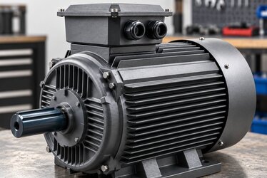
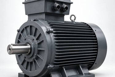
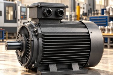
- Roots (two-lobe) and rotary lobe (three-lobe) blowers: These are positive displacement machines. The motor usually stands foot-mounted on a common baseframe and drives the blower through a belt and pulleys. Some packaged units also use direct drive through a coupling. In both cases a standard IEC frame three-phase motor is a natural part of the application.
- Side channel blowers: The motor and blower are often built as a single unit; the impeller is mounted directly on the motor shaft and the frame may be specific to the blower. With this type, the motor can be replaced by a standard model only if the existing motor is a standard IEC flange motor. For motors with a special shaft or special frame, the special motor requirement should be asked about with the nameplate and technical information.
- Centrifugal (turbo) blowers: These run at high speed and often come with drive systems specific to their manufacturer; they are outside the scope of this article.
Load type: a blower is a constant torque machine
Roots and lobe blowers do not behave like fans. In a fan, the power drawn falls quickly as speed drops; in a positive displacement blower, as long as the back pressure stays constant, the torque on the shaft stays roughly the same. The power requirement depends mainly on two things: the blower speed (that is, the amount of air delivered) and the back pressure coming from the basin depth. When the basin water level rises or the diffusers clog, the pressure rises and so does the current drawn by the motor.
For this reason, motor power is determined from the blower manufacturer's operating point data (flow, pressure difference, required shaft power). Belt losses and the pressure increase that may later come from diffuser fouling are also taken into account. Power is not determined by looking at the machine's name; the same blower model needs different power at different basin depths.
Starting
Blowers are generally started with the blow-off valve open, that is, so that they start unloaded. If the valve is faulty or closed, the motor has to start against full pressure and the start becomes heavy. The starting method (direct, star-delta, soft starter or drive) should be stated with the order. If star-delta starting is to be used, a motor labelled 400/690 V that runs in delta on a 400 V supply is needed; HEM Motor's models of 4 kW and above have this voltage rating.
Speed: the decision for belt and coupling drives
In a belt-and-pulley drive the blower speed is set by the pulley ratio; thanks to this flexibility a 4-pole (1,500 rpm synchronous) or 2-pole (3,000 rpm synchronous) motor can be used. If you are replacing the motor in an existing system, keep the number of poles; otherwise the pulley calculation must be redone from scratch. In direct drive through a coupling, the blower speed equals the motor's rated speed and the motor choice depends directly on the blower's design speed.
In a belt arrangement the motor bearings carry the radial load caused by belt tension. The pulley should be fitted as close to the motor as possible on the shaft and belt tension kept at the blower manufacturer's value. An over-tensioned belt is one of the main reasons for shortened bearing life in a continuously running motor.
Continuous operation and environmental conditions
The blower motor runs in S1 continuous duty. A standard motor with S1 on its nameplate is designed for this job; but continuous operation has a consequence: the motor runs constantly close to rated load without any chance to cool down. That is why it is very important that the motor's own fan can draw fresh air.
- Acoustic enclosure: Blowers often run inside an acoustic enclosure. If enclosure ventilation is inadequate, the temperature inside rises noticeably above the outside ambient. The fact that the motor is inside an enclosure and the ambient temperature inside it are stated with the order.
- Outdoors: At outdoor blower stations the motor is exposed to rain, direct sun and dusty wind. IP55 protection guards against water jets and dust; even so, a canopy or protective roof is beneficial for motor life.
- Humidity and condensation: In a treatment plant the air can be saturated with moisture. In standby motors, the difference between day and night temperatures can cause condensation inside the frame. If there is a standby motor that will not run for long periods, this is stated with the order; standby motors should be run briefly at regular intervals.
- Gas and vapour: Corrosive gases may be present in the pre-treatment and sludge sections. The blower station should be in a place separate from these areas that takes in clean air.
Under these conditions the cast iron frame is often preferred for its rigidity and resistance to external effects. All our models on sale have IP55 protection and class F insulation.