English
 Français
 Türkçe
 Español
 Русский

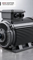
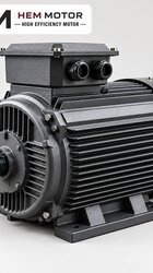
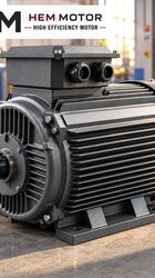
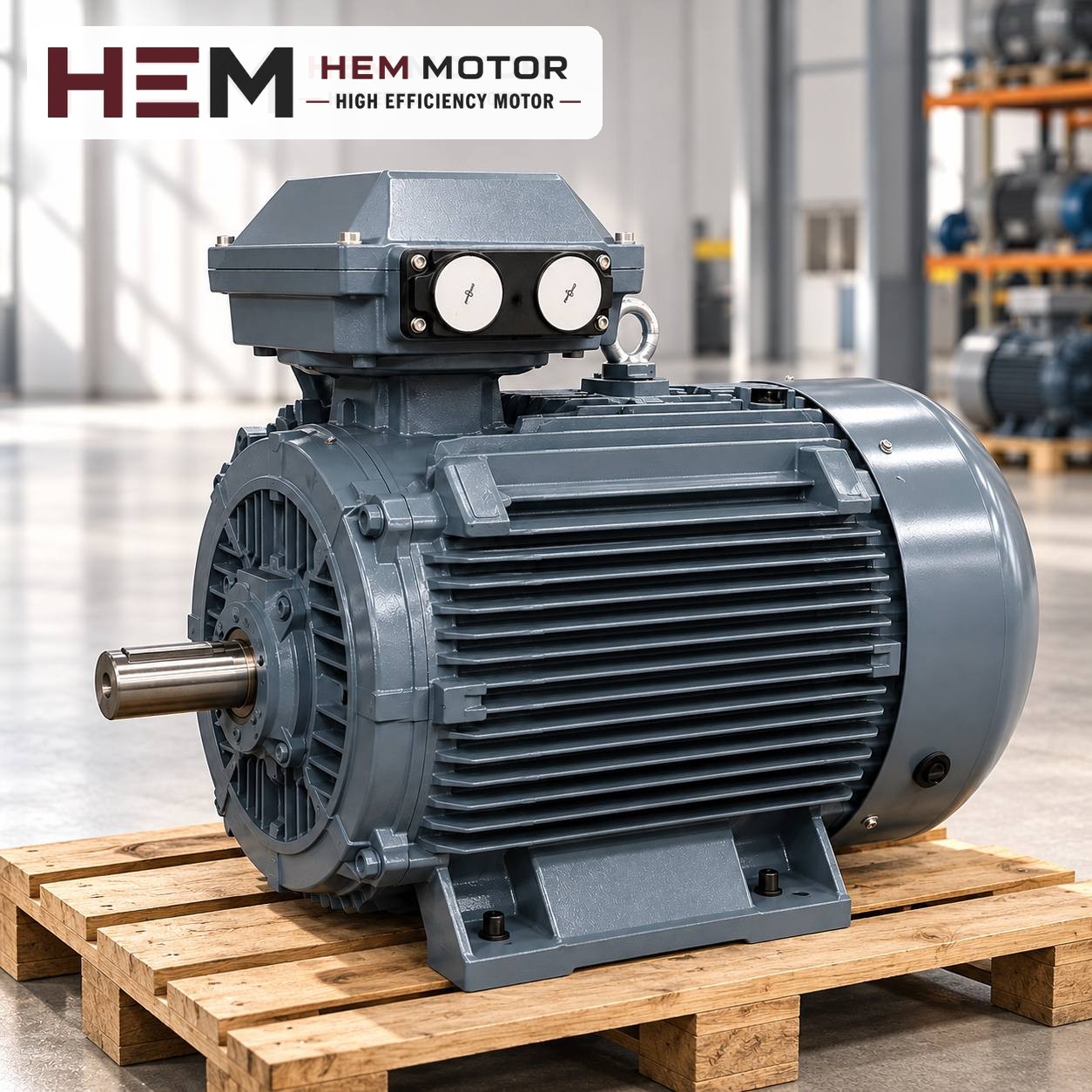

Replacing the motor on a horizontal water pump is often thought of as "find a motor with the same power and speed, then fit it". In reality, the main part of the job is making sure the new motor's shaft end matches the coupling hub, its shaft height matches the pump axis and its foot holes match the baseplate. If any of these three points is off, the pump will show it within the first days through vibration, gland leakage and bearing noise.
This article focuses on renewing horizontal-shaft motors that sit on a baseplate and drive the pump through a flexible coupling. We explain, step by step, which information to take from the old motor, what the IEC frame code tells you and why alignment is an inseparable part of the replacement.
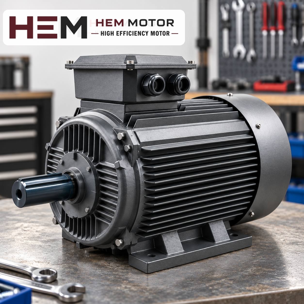
First identify the pump layout: coupled or close-coupled?
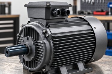
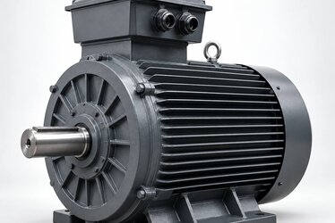
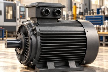
Horizontal pumps are found in two main layouts on site. In the first, the pump and motor stand on a common baseplate; the motor is bolted down by its feet and a flexible coupling connects the two shafts. In this layout the motor is a standard IEC-dimensioned, foot-mounted (B3) motor, and once the correct frame is chosen the replacement is mechanically simple.
The second layout is the close-coupled (monobloc) pump: the pump casing sits on the motor's front flange and the impeller is often mounted directly on the motor shaft. In these designs the shaft length, shaft-end machining and flange are specific to the pump manufacturer. Such a motor is not equivalent to a standard motor; a special-shaft motor is required, which may fall outside the scope of the standard range in HEM Motor's 2026 catalogue. In that case, ask us with the nameplate and a photo of the shaft.
In the coupled layout, check one more detail: if the coupling is a spacer type, the pump can be removed without moving the motor. The gap between the two shaft ends is then set by the spacer length, and the shaft shoulder of the new motor must come to the same point.
Information to take from the old motor
- Nameplate values: Power (kW), rated speed (e.g. 2,930 rpm), voltage and connection (Δ/Y), frequency. Do not change the speed, because the pump's impeller diameter and head are designed for it.
- IEC frame code: such as 132S or 160M. If the code is the same, the shaft height and foot hole spacing are the same by standard.
- Shaft end: Shaft diameter, shaft extension length and key width. Measure with a caliper and also note the bore of the coupling hub.
- Direction of rotation: Look at the arrow on the pump casing. On a three-phase motor the direction is reversed by swapping two phases; it must always be checked at first start-up.
- Baseplate condition: Shim plates, foot bolts, cracks or corrosion on the baseplate.
On motors whose nameplate cannot be read, the most reliable way to find the frame code is to measure the height from the shaft centre to the bottom of the feet. The IEC frame number gives this height in millimetres; on a 132 frame the shaft height is 132 mm.
Shaft end and coupling hub fit
On standard IEC motors, shaft diameter and length depend on the frame code and the number of poles. On some of the larger frames, the shaft of a two-pole motor is thinner than that of a four-pole motor in the same frame. So "same frame" does not always mean "same shaft". If you plan to take the coupling hub off the old motor and fit it on the new one, the shaft diameter and key size must match exactly.
If the dimensions differ, there are two options: renew the motor-side coupling hub for the new shaft diameter, or choose another model whose dimensions match. Forcing the hub on with a hammer stresses the shaft and bearings from the very first installation; the hub should be fitted by heating it or with a suitable puller/press tool. You can compare shaft and key dimensions in the 2026 technical and product catalogue. We do not give dimension values here, because they must be confirmed for the frame before ordering.
Shaft height, foot holes and baseplate
Since the pump axis is fixed, the shaft axis of the new motor must be at the same height. The same IEC frame code ensures this. If a motor with a different frame is chosen, an adapter plate must be made for the baseplate or the baseplate must be re-drilled; both options lengthen the labour and alignment time.
The letter in the frame code (S, M, L) indicates the longitudinal distance between the foot holes. 160M and 160L have the same shaft height but their foot holes are in different places. On some frames the feet may have holes for both dimensions; confirm this from the drawing. The 2D technical drawings prepared by frame size can be used for this comparison.
Coupled pump motors usually run foot-mounted (B3). According to the general information on our site, B3, B5, B14, B34, B35 and vertical V1/V3/V5/V6/V15 arrangements are offered according to the frame; the flange size is confirmed with the order.