English
 Français
 Türkçe
 Español
 Русский




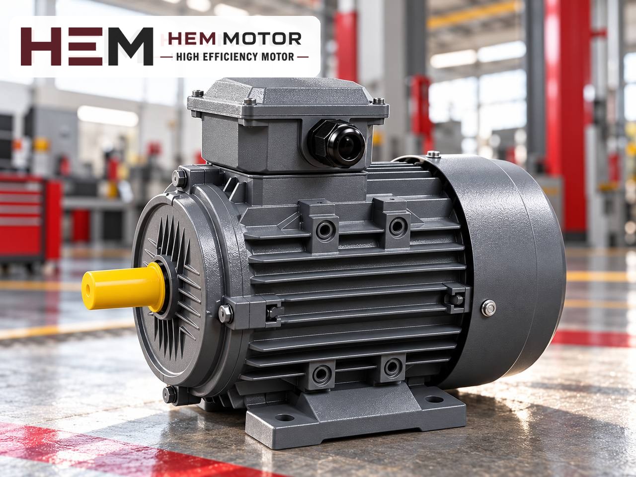

When choosing the motor for a centrifugal (scroll-housing) fan, first find the speed at which the impeller must turn, then calculate the power the fan draws at that speed, and finally determine the pulley ratio that bridges the difference between motor speed and impeller speed. The order matters: choosing a pulley "from whatever is to hand" changes both the fan's airflow and the motor's load at the same time. This article explains these three steps for belt-driven centrifugal fans with numerical examples.
Step 1: where does the impeller speed come from?
The airflow and pressure of a centrifugal (radial) fan depend on the impeller's diameter, blade design and speed. The fan manufacturer gives this relationship in the fan curve or selection table. When the airflow and system pressure the plant needs are entered in this table, a corresponding impeller speed is read. This is the starting point for motor selection, not the motor's own speed.
If you are renewing the motor of an existing fan, you can also find the impeller speed on site: use the rated speed on the motor nameplate, the motor pulley diameter and the fan pulley diameter.
Impeller speed = Motor speed × Motor pulley diameter / Fan pulley diameter
For example, with a 1,460 rpm motor, a 150 mm motor pulley and a 200 mm fan pulley, the impeller turns at about 1,095 rpm. Pulley diameters should be taken at the pitch (effective) diameter where the belt sits; a calculation made with the outside diameter gives a small but measurable deviation.
Step 2: how many kW does the fan draw at that speed?
The power the fan requires at the shaft is found by dividing the power it transfers to the air by the fan efficiency:
Shaft power (kW) = Airflow (m³/s) × Total pressure (Pa) / (1000 × fan efficiency)
If the airflow is known in m³/h, divide it by 3,600 to convert it to m³/s. The fan efficiency is read at the operating point on the fan curve. A margin is added to this value for belt transmission losses and deviations that may occur in operation, and then the first standard motor power above it is chosen.
Because the relationship between power and speed is steep in fans, small errors in the speed calculation appear magnified in the power. According to the fan laws, in the same system:
- Airflow changes in direct proportion to speed.
- Pressure changes with the square of speed.
- Power changes with the cube of speed: if impeller speed rises by 10%, the power drawn rises by about 33%.
So reducing the fan pulley "to increase the airflow a little" can quickly push the motor into overload. If the pulleys are to be changed, the power requirement at the new speed must be recalculated and the impeller's maximum permissible speed confirmed with the fan manufacturer.
Watch out at start-up: backward-curved and forward-curved impellers
With backward-curved impellers, the power curve peaks and does not much exceed a certain value even as airflow increases; the motor is chosen for this peak. With forward-curved (multi-vane) impellers, however, power keeps rising with airflow. If such a fan runs without ductwork or with the damper fully open, the motor can exceed its rated current. State the fan type and damper arrangement with the order.
Step 3: pulley ratio and motor pole number
Which motor speed is used to reach the required impeller speed determines the pulley ratio. Belt-driven fans most often use a four-pole (1,500 rpm synchronous) motor, because many fan speeds can be reached with a reasonable ratio. For very high impeller speeds a two-pole motor comes into play, and for large, slow-running impellers a six-pole motor.
| Target impeller speed | Motor (rated speed) | Pulley ratio (fan/motor) | Comment |
|---|---|---|---|
| 1,100 rpm | 4-pole, 1,460 rpm | ≈ 1.33 | Balanced ratio, common choice |
| 1,100 rpm | 2-pole, 2,930 rpm | ≈ 2.66 | Motor pulley becomes small, belt and bearing load increase |
| 750 rpm | 6-pole, 970 rpm | ≈ 1.29 | Can be considered for large, slow impellers |
| 750 rpm | 4-pole, 1,460 rpm | ≈ 1.95 | Feasible; the fan pulley becomes larger |
The values in the table are calculation examples. As the ratio increases, either the motor pulley becomes smaller or the fan pulley larger. A small motor pulley transmits the same power with a higher belt force, which loads the motor shaft and the drive-end bearing more. Do not go below the minimum pulley diameter recommended by belt manufacturers for each belt profile.
Motor-side checks in the belt and pulley arrangement
- Pulley position: Fit the motor pulley as close as possible to the shaft shoulder. The further the pulley sits out on the shaft end, the greater the moment on the bearing.
- Belt tension: An over-tight belt loads the bearing; a slack belt slips and heats the belt and pulley. Mounting the motor on slide rails makes adjustment easier.
- Pulley alignment: The faces of the two pulleys must be in the same plane. Misaligned pulleys wear the belt on its side and create vibration.
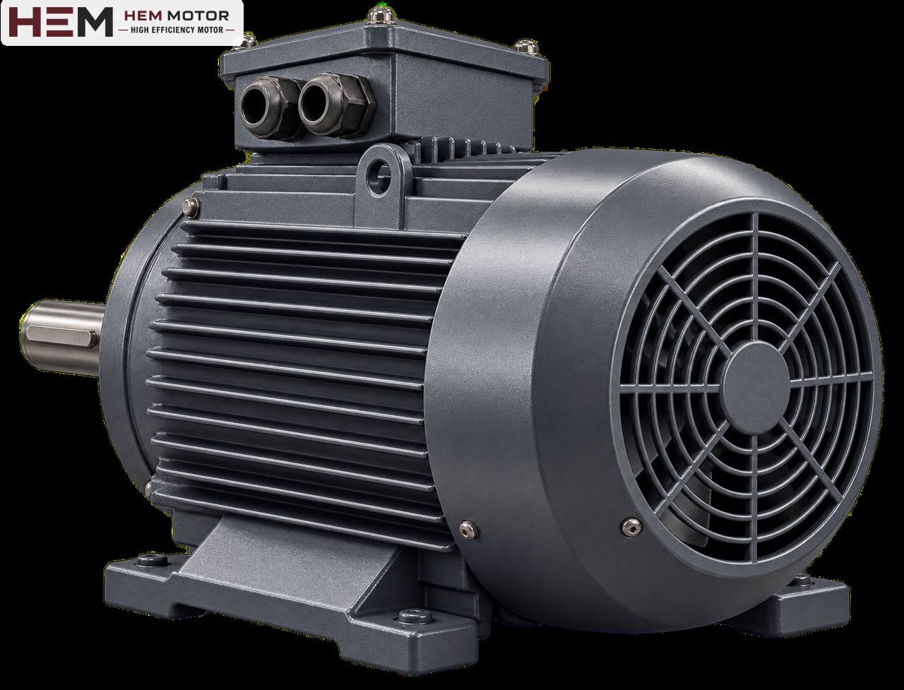
- Mounting arrangement: On belt-driven fans, the motor is usually foot-mounted (B3) and sits on the fan frame or on slide rails. According to the general information on our site, B3, B5, B14, B34, B35 and vertical V1/V3/V5/V6/V15 arrangements are offered according to the frame; the flange size is confirmed with the order.
- Shaft end: If the existing pulley is to be fitted to the new motor, the shaft diameter and key size must match the pulley hub. Dimensions are in the 2026 technical and product catalogue.
Browse suitable HEM Motor models and current prices in the online sales section. Information specific to fan applications is on the industrial fan motors page.