English
 Français
 Türkçe
 Español
 Русский

A four-sided planer, known in the trade as a profile machine or moulder, machines timber on all four faces in a single pass and produces long parts such as dimensioned battens, panelling, skirting boards, door casings and window profiles. Here it is not one motor but a separate motor for each machining spindle, together with the feed drive, that does the work. This page covers that group of motors; for all woodworking machines, see our Woodworking Machine Electric Motors page.

Spindle Sequence and the Job of Each Spindle
The timber is taken in at the machine entrance against a fence and passes through the machining stations in turn. In a typical layout the bottom horizontal spindle first flattens the underside. Then the right and left vertical spindles bring the two edges to size; finally the top horizontal spindle gives the thickness. Larger machines add a second top or bottom spindle, or a universal spindle that can be turned in any direction, so the number of spindles can rise from four to eight or even more.
Each spindle turns with its own motor. On small machines the motor is connected to the spindle by belt; in more advanced designs the tool holder sits directly on the motor shaft or on a dedicated spindle bearing flanged to the motor. This difference changes motor selection: in the belt layout the foot-mounted frame and pulley matter, in the direct layout the flange size and shaft tolerance are decisive.
Profile Cutter and Load per Spindle
Thinking of all spindles as equal in power is misleading. A spindle that cleans a flat surface removes little material, while one cutting a deep profile removes far more chips at the same feed. That is why the motor on the profiling spindle is often kept larger than the others, and feed speed is reduced as the profile gets deeper.
Wood species also sets the load. The same machine producing softwood panelling and machining hardwood oak casings loads its spindles differently at the same feed speed. When replacing a motor, go by the value on that spindle's nameplate and the power the machine maker gives for that station; do not guess from the spindle's position.
Because tool speed is high, spindle motors are usually two-pole, in the 3000 rpm class; higher tool speeds are reached by pulley ratio or a machine-specific high-speed spindle unit. Such high-frequency special spindle motors are not part of HEM Motor's 2026 catalogue; this page covers spindles driven by a standard IEC motor.
Feed Drive and Beam Adjustment
The timber is pushed by driven wheels arranged along a beam above the machine. These wheels take their motion from a common feed motor through a gearbox and cardan shafts in between. The load comes from the force needed to push the piece against the cutters and behaves as a constant-torque load.
Feed speed is changed for different jobs. Older machines have a pole-changing two-speed motor or a stepped gearbox; on newer machines the feed motor is mostly driven by a frequency converter. The three-phase motors in our range can run on an inverter. A motor expected to carry full load for hours at low feed speed may find its own fan insufficient; in that case a separately powered cooling fan is considered, and an output filter is evaluated if a long cable runs from drive to motor. Simply stating these when you request a quotation is enough.
When the timber thickness changes, the beam carrying the top spindle and the pressure wheels together is adjusted up or down by a small motor. This motor runs briefly, changes direction often and needs little power.
Sequential Starting and Supply Load
Electrically, the most distinctive feature of a four-sided planer is that it has many motors at once. If all spindle motors were started direct-on-line with a single button at the same moment, their starting currents would stack up and the panel fuse or transformer might not withstand the surge. That is why machines have a separate button for each spindle, and the operator brings the motors in one by one, starting the next once the previous one has reached speed.
On large spindle motors, a star-delta connection or a soft starter completes this sequence. Star-delta can only be used if the winding can be connected in delta on a 400 V supply; the 400/690 V rated motors in our range meet this condition. Starting order and interlocks belong to the machine's control circuit; after a motor replacement, check that it still works with the same logic.
Mounting, Chips and Maintenance
Vertical spindles carry the motor upright. For a motor that will run vertically with the shaft pointing up or down, state the mounting type clearly in the order; depending on frame, our motors are available in horizontal B3, B5, B14, B34, B35 and vertical V1, V3, V5, V6, V15 positions, and flange and shaft dimensions are confirmed at quotation stage. For details, see the flange-mounted electric motors page.
Inside the closed cabin of a moulder, chips and fine dust circulate together. Extraction is taken separately from each spindle hood; when one outlet clogs, that spindle's motor gets covered in chips and heats up. The IP55 enclosure keeps chips from getting in, but it does not clean off chips covering the fan cowl; motors inside the cabin should be blown clean regularly. Bearing noise and vibration are the first signs of trouble in the spindle bearings.
Example Motors for a Moulder
| Drive | Connection | Value to check | Example HEM model |
|---|---|---|---|
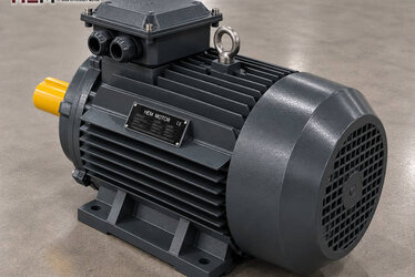
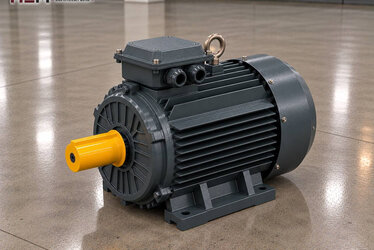
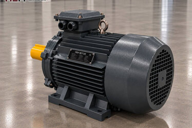
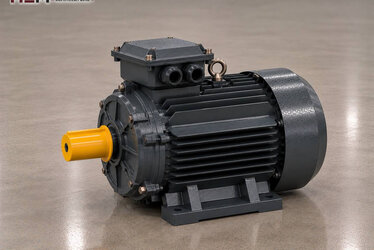
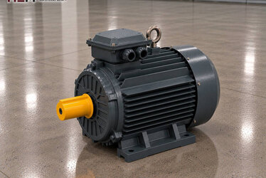
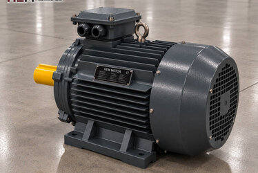
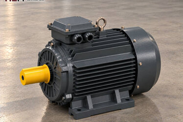
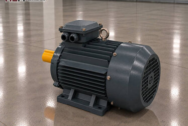
| Planing spindle (bottom or top) | Belt or direct | Working width, shaft size | 5.5 kW 132S1-2 (2,930 rpm) |
| Profiling spindle | Belt or direct | Profile depth, wood species | 11 kW 160M1-2 (2,945 rpm) |
| Vertical edge spindles | Vertical mounting, flanged | Mounting position, flange type | 4 kW 112M-2 (2,905 rpm) |
| Feed wheels | Gearbox and cardan | Lowest speed on inverter | 2.2 kW 100L1-4 (1,450 rpm) |
| Beam lifting | Screw spindle | Short two-way duty | 0.55 kW 80M1-4 (1,400 rpm) |
The table is only a pointer: which motor is suitable is decided by looking together at that spindle's chip load, required tool speed, the motor's mounting position and the workshop environment. Each spindle's own nameplate must be considered separately.
Quotation for a Four-Sided Planer Motor
Tell us which spindle the motor to be replaced belongs to (bottom, top, right, left, universal or feed), the machine type, the power and speed, the voltage, the mounting position and the quantity. If several motors are to be replaced, photograph each nameplate separately; our send your motor nameplate article will help.
You can see all our models with current prices on our shop page, and use our contact details to reach us by WhatsApp or phone.
Frequently Asked Questions
Is it right to buy all spindle motors at the same power?
Usually not. Because the profiling spindle removes more chips, on most machines it carries a stronger motor. Go by the value on each spindle's nameplate separately.
Can I replace a vertical spindle's motor with a horizontal one?
A motor in a mounting type suitable for vertical running must be chosen; details such as bearing arrangement and drip cover vary with position. State the mounting position and shaft direction in the order.
My feed motor is two-speed; what can I use instead?
Instead of a pole-changing motor with a special winding, a single-speed standard motor and a frequency converter can be used. Since this change also affects the control circuit, assess it together with the machine diagram.
Why are spindle motors started one after another?
If the starting currents of the motors add up at the same moment, the supply is strained. Sequential starting spreads this sudden load; star-delta or a soft starter can also be added to the stronger spindle motors.