English
 Français
 Türkçe
 Español
 Русский

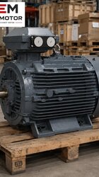
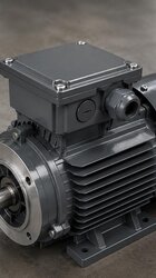

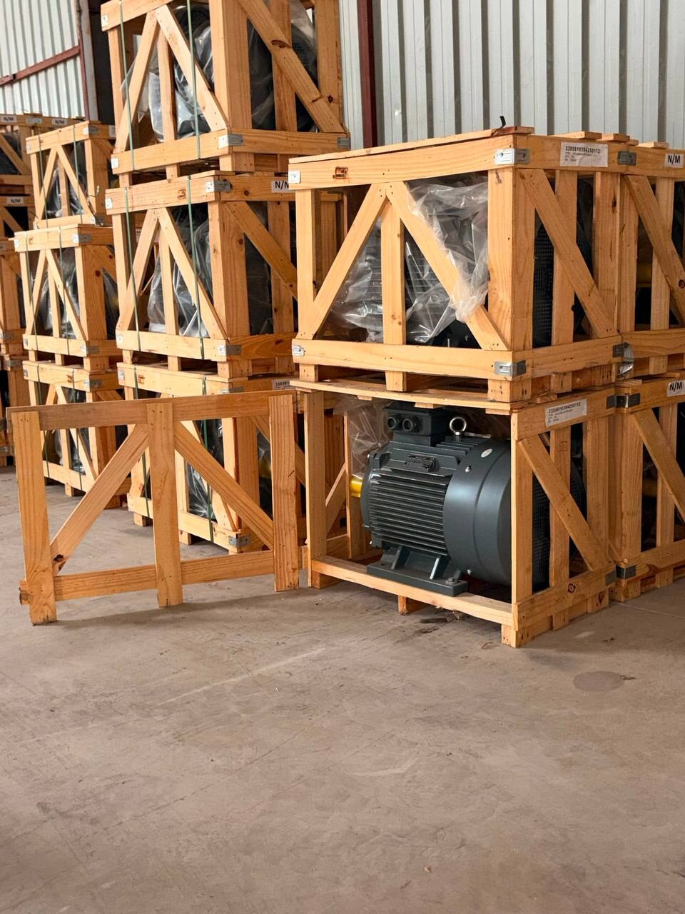

A feed grinding machine, in other words a hammer mill, is one of the machines in a feed plant that consumes the most energy and puts the most strain on its motor. Barley, maize, wheat or bran is broken up by hammers on a rotating rotor and passes through a screen to reach the desired fineness. Since the range is wide, from small farm machines to plant mills processing tonnes of product per hour, the question "what kW motor does a feed grinder need?" has no single answer. In this article we explain the factors that determine motor power, from whom and how the power should be obtained, the choice of speed and transmission, and the information to be provided with the order.
Factors that determine the power requirement
The power drawn by a hammer mill depends less on the value written on the machine's nameplate than on what is fed into it that day. The main variables that change the power requirement on the same machine are:
- Type of raw material: Hard grains such as maize and barley require much more energy than bran or pre-broken product. Fibrous materials such as dry hay or straw load the hammers in a different way.
- Screen hole diameter: When a screen with small holes is used for fine grinding, the product stays longer in the mill and the power for the same capacity rises markedly. Changing the screen actually means changing the load on the motor.
- Moisture: Moist grain does not break easily, clogs the screen and builds up around the rotor; as a result the current rises.
- Capacity (feed rate): The more the feed screw or gate is opened, the more the motor is loaded. When the mill is fed more than the motor can carry, the speed drops first and then the protection trips.
- Number of hammers and their wear: Hammers with blunt tips rub the grain instead of breaking it; more power is spent for the same work and heat increases.
- Operating time: A farm machine running one or two hours a day and a plant mill running non-stop through a shift wear the motor differently, even at the same power.
That is why giving a fixed table such as "this capacity needs this kW" would be misleading. The right way to determine motor power is to follow the sequence described below.
Who determines the power, and how?
On a new machine, the power is the machine manufacturer's value. The manufacturer has designed the rotor diameter, the hammer arrangement, the screen area and the target capacity around this power; fitting a smaller motor limits the machine, while fitting a much larger one may stress mechanical parts such as the rotor, bearings and belts beyond their design limits.
If the motor of an existing machine is being replaced, the information to rely on is the old motor's nameplate: power, speed, voltage and IEC frame code. If the old motor ran for years without problems, a motor with the same values is the safest choice. If the motor trips the thermal relay frequently or overheats, the following questions should be asked before increasing the power: Was the screen replaced with a finer one? Did the raw material change? Are the hammers worn? Was the feed setting changed? Are the belts slipping? Most of these problems are solved not by enlarging the motor but by correcting the machine itself.
If moving to a larger motor is genuinely necessary, for example when a capacity increase is planned, the decision should be taken together with the machine manufacturer. Whether the rotor, shaft and belt arrangement can withstand the new power can only be assessed on the machine side.
What does a current measurement tell you?
The practical way to understand how heavily the motor is really loaded on a running mill is to measure the phase currents with a clamp meter under normal feed. If the measured current is very close to or above the rated current on the nameplate, the motor is working at its limit. If it is clearly below, the motor is comfortable and the source of the overheating problem should be looked for elsewhere. This measurement bases the replacement decision on data rather than guesswork.
Speed and transmission: direct coupling or belt and pulley?
In hammer mills the rotor usually turns at a high peripheral speed; for this reason, on many machines a 2-pole (3,000 rpm synchronous) motor is connected directly to the rotor with a coupling. In this arrangement the rotor speed equals the motor speed and the motor speed cannot be changed. On some machines a 4-pole motor turns the rotor through belts and pulleys; the pulley ratio determines the rotor speed.
- Direct coupled arrangement: The motor speed must be the same as the speed required by the machine manufacturer. The foot-mounted (B3) motor is aligned with the rotor on a common baseplate; the shaft height and foot spacing are compared with the old motor.
- Belt and pulley arrangement: If the motor speed changes, the rotor speed changes too. Replacing a 1,500 rpm motor with a 3,000 rpm motor doubles the rotor speed if the pulleys are not changed; this is dangerous for both the hammers and the bearings. Speed is not changed without recalculating the pulley ratio.
- Belt tension: An over-tightened belt puts a side load on the motor's front bearing; a loose belt slips, heats up and wastes part of the power.
Because the rotor speed is high, imbalance also matters. If one of the hammers is broken or missing, the resulting vibration is transmitted to the motor bearings. If the real cause of the old bearing failure was such an imbalance, the new motor will soon meet the same end.