English
 Français
 Türkçe
 Español
 Русский

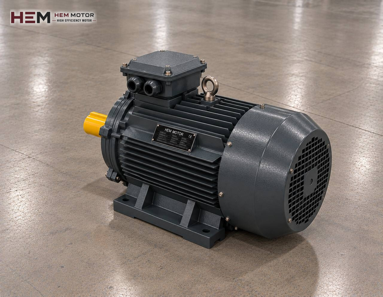
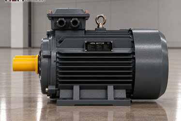
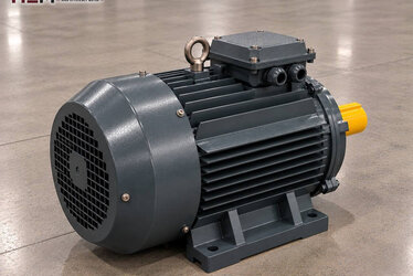
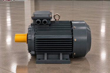
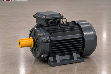
Loose cardboard, stretch film, PET bottles, tin cans or textile offcuts take up a lot of space in storage; a baling press turns this material into tied, stackable blocks. This page covers the three-phase electric motor inside the press; for the other machines on site you can return to the waste processing and recycling machine electric motors page.

How a Bale Is Formed: The Cycle Step by Step
An operator or an infeed conveyor fills the chamber with material. Once the door closes, the platen moves down (on vertical presses) or forward (on horizontal presses) and compresses the material.
The platen retracts, the chamber is filled again, and this loop repeats until the bale reaches the required size. Finally wire or strapping is passed through and the bale is pushed out. On horizontal presses with automatic tying, tying and ejection are fed from the same hydraulic circuit.
What matters for the motor is this: every cycle brings a short moment of high load, followed by a return stroke and a pause that run almost unloaded.
Telling a Hydraulic Press from a Mechanical Baler
Most baling presses used in recycling plants are hydraulic. In these machines the compaction force comes from the cylinder and oil pressure; the electric motor only turns the hydraulic pump. The tonnage of the press depends on cylinder bore and pressure and does not directly indicate motor power.
Mechanical balers working with a crank, chain or flywheel are less common. There the motor accelerates a heavy flywheel, which releases its stored energy at the moment of compression. In this layout start-up takes long and the motor has to carry this acceleration without overheating. Confirm which type you have from the machine plate or the manufacturer's documents; the motor is selected with a different logic for each type.
From Pump Flow and Pressure to Motor Power
On a hydraulic press the two values that define the motor are the oil flow delivered by the pump and the highest working pressure. For a rough estimate this relation is useful: power (kW) ≈ flow (l/min) × pressure (bar) ÷ (600 × η). The η in the denominator is the pump and system efficiency; the formula gives an approximate result, and the exact value comes from the pump manufacturer's data.
Many presses use high flow for rapid approach and high pressure for final compaction. With two-stage or pressure-compensated pumps these two conditions do not peak at the same time, so the motor power can stay smaller. That is why basing the choice on flow alone or pressure alone is misleading.
If you are replacing an old motor, its nameplate is the most reliable starting point. If a larger pump will be fitted to shorten the cycle time, the motor must be reassessed as well. For detailed calculation and coupling topics see the electric motors for hydraulic pumps page.
Start-Up, Idle Time and Direction of Rotation
In a hydraulic unit the pump usually starts unloaded: oil returns to the tank without pressure, and the valve only switches in after the motor reaches speed. Thanks to this, star-delta or a soft starter handles start-up comfortably on most presses.
Some presses stop the motor after each bale, others keep it idling during the pause. In a layout with frequent stops and starts the winding temperature rises; if there are many starts per hour, a PTC or PT100 sensor can be added to the winding on order.
Direction of rotation is critical for the pump. After connecting the new motor, check the direction with a short run; a pump turning backwards cannot deliver oil and may be damaged. If the phase sequence has changed, swapping two phases is enough.
Connecting the Motor to the Pump
On power units the motor usually sits horizontally on top of the tank and is connected to the pump through a bell housing and a flexible coupling. The arrangement most often found on press units is a B5 flange or a B35 (foot plus flange) motor; on compact units placed upright beside the tank the motor runs in the V1 position.
Depending on frame size, foot-mounted B3, flange-mounted B5 or B14, B34 or B35 combining foot and flange, and vertical V1, V3, V5, V6 or V15 versions can be supplied. We check the flange diameter that will sit on the pump bell and the shaft dimension together with you before the order. For flange options see flange-mounted electric motors, and where foot and flange are both needed see the B34 and B35 motors page.
Coupling misalignment is one of the most frequent causes of failure for the bearings and the pump shaft; check the alignment again after replacing the motor.
Cardboard Dust, Oil Heat and Maintenance
Where cardboard and paper are baled, fine fibres and dust stick to the motor's cooling fins. When the grille of the fan cover clogs, cooling air drops and the motor runs hotter than normal; the cover and frame should therefore be cleaned at regular intervals.
As the hydraulic tank warms up, the air next to the motor warms up too. If the oil cooler is undersized the problem shows up in the oil before the motor, but the motor still ends up working in a hotter environment. For presses standing outdoors or in damp warehouses, an anti-condensation heater is an order option.
On baling presses the pump usually turns at a fixed speed, but some manufacturers adjust the flow with a drive. Our three-phase motors can be driven by a frequency inverter. If the motor will run slowly at full load for long periods its own fan may not be enough and a separate cooling fan is added; when the cable between drive and motor is long, a dv/dt or sine filter at the output is considered. Write these two conditions in your order note. On this topic, see the inverter question.
Example Models by Press Type
| Press type | Motor load | Value to check | Example HEM model |
|---|---|---|---|
| Small vertical cardboard press | Short compression, long pause | Starts per hour | 3 kW, 1,450 rpm, 100L2-4 |
| Medium vertical press | Peak load set by pump pressure | Pump flow and pressure | 7.5 kW, 1,460 rpm, 132M-4 |
| Semi-automatic horizontal press | Long shifts, frequent cycles | Cycle time, oil temperature | 15 kW, 1,465 rpm, 160L-4 |
| Channel press with automatic tying | Continuous operation with infeed conveyor | Pump group, starting method | 22 kW, 1,470 rpm, 180L-4 |
The models in the rows are only meant to give an idea; the final decision depends on the press load, the speed required by the pump, the mounting arrangement and the operating conditions. The powers listed are the range commonly seen on this kind of press; compare them with the nameplate of your current motor.
Information Needed for a Quotation
So that we can suggest the right motor quickly, write the following in a single message: machine type and press type, power of the old motor (kW), speed in rpm, the voltage at your plant, the motor's mounting arrangement (B5, B35, V1 etc.) and the quantity required. Add the pump's flow and pressure values if you know them.
If the old motor's plate is readable, a photo is enough; follow the steps on the find an equivalent from the nameplate page. You can see models and current prices in the electric motor shop, and use the contact page for WhatsApp or phone.
Frequently Asked Questions
Why is a baling press motor usually chosen in the 1,500 rpm class?
Most hydraulic pumps are designed for this speed range and their flow ratings are given at this speed. If the pump manufacturer specifies a different speed, the motor is chosen accordingly.
Will the press compact harder if I fit a more powerful motor?
No. Compaction force is set by the cylinder bore and the pressure adjusted at the relief valve. A more powerful motor alone does not raise the force; if the pump stays the same, the cycle time does not change noticeably either.
I connected the new motor and the press builds no pressure; can the motor be the cause?
The first thing to check is the direction of rotation. A pump turning backwards delivers no oil; swap two phases and try again. If the direction is correct, the valve and pump side should be checked.
Should the motor idle or stop during the pause?
This depends on the press control scheme. Frequent stop-start heats the winding, while continuous idling heats the oil. Assess the number of bales per hour and the pause time with the machine manufacturer and tell us in your order.
Are these motors also suitable for an agricultural straw baler?
Field balers driven from a tractor PTO have no electric motor. If there is a stationary, electrically driven baling unit, we select the motor from load and mounting information as described on this page.