English
 Français
 Türkçe
 Español
 Русский

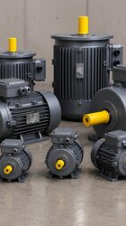
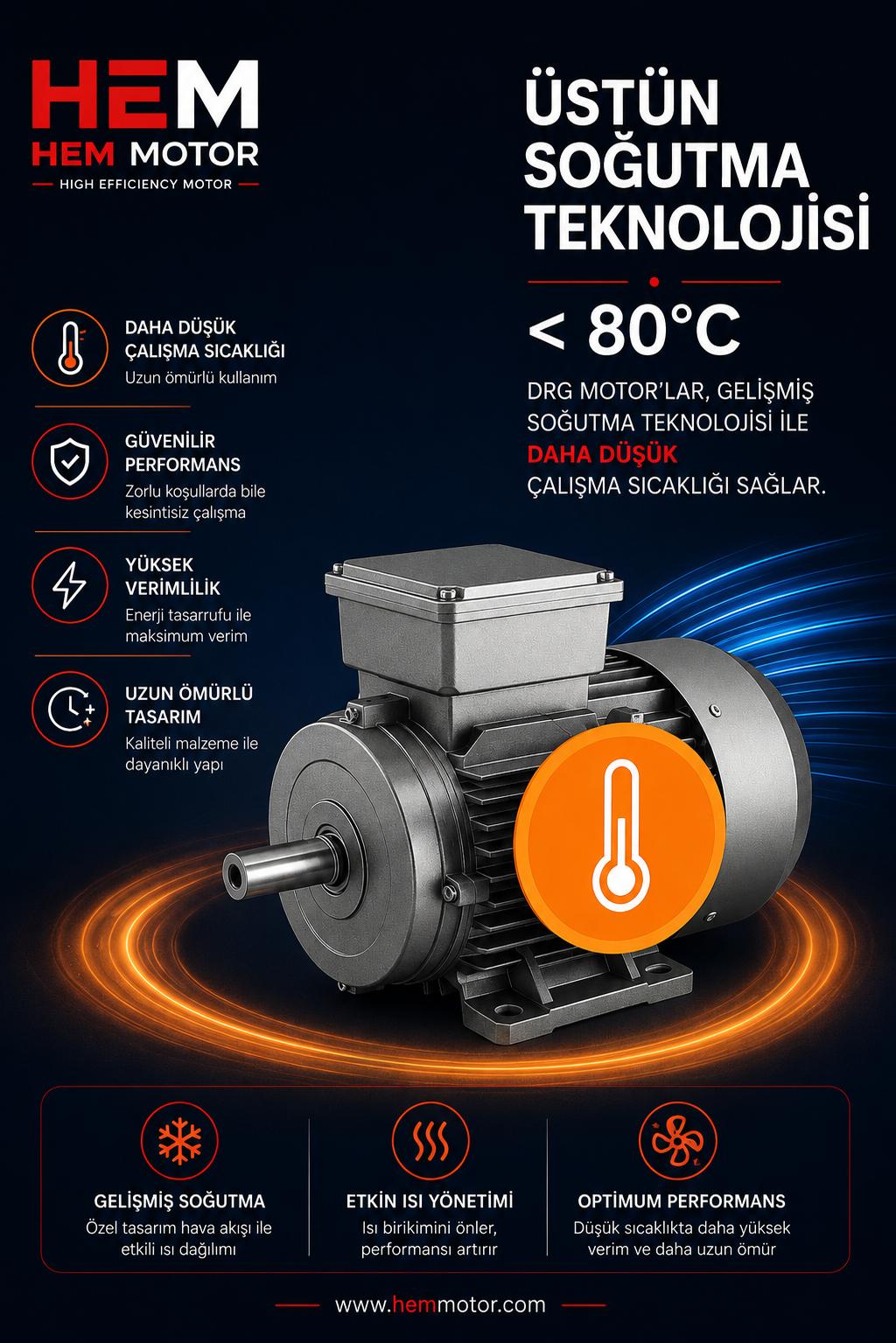

It is commissioning day. The electrician opens the terminal box and finds two thin leads next to the three power terminals: the PTC sensors embedded in the winding. The panel, however, has no thermistor relay to connect them to. Either the leads are taped off and the motor starts life without temperature protection, or the start-up slips by a week. The reverse happens just as often: the panel builder fitted a relay with a PTC input, the motor arrives without sensors, and someone bridges the input.
Both cases have the same root cause. The motor and the control panel were bought separately, by people who never compared notes. Protection is a chain that runs from parts inside the motor to devices in the panel, and it needs to be specified as one.
Two halves of the protection chain
It helps to split the protective elements of an induction motor into two groups:
- On or inside the motor: winding temperature sensors (PTC or PT100), an anti-condensation heater, auxiliary terminals in the terminal box, cable entries, and on large frames fed by a drive, an insulated bearing or shaft grounding. These are fitted at the factory. Adding them later is difficult or impossible.
- In the panel: short-circuit protection (fuses or a motor protection circuit breaker), overload protection (thermal or electronic relay), phase loss and phase sequence monitoring, the evaluation relay the sensor connects to, the contact that switches the heater, and the starter itself.
The first group belongs on the motor purchase order, the second on the panel order. The trouble is that the two orders usually leave different desks. We covered which device reacts to which fault in our article on thermal relays, fuses and MPCBs; this one is about making the two halves match.
Protection items to add to the motor order
Winding temperature sensors
Current-based devices only estimate how hot a motor is getting. With a clogged fan cowl, a hot plant room, or long running at low speed on a drive, the current can look normal while the winding overheats. Sensors are worth specifying for drive-fed motors, frequent starts and hot locations. On HEM Motor three-phase series, PTC and PT100 are options chosen at the order stage. The choice also dictates the panel device: a PTC trips a relay at a fixed threshold, while a PT100 feeds an input that reads temperature continuously. Our guide to PT100 and PTC winding sensors covers settings in detail.
Anti-condensation heater
Motors that stand idle for long periods, sit outdoors, or see large day–night temperature swings collect moisture inside the housing. The heater is energised while the motor is stopped and switched off when it runs. That means the panel needs a separate supply and an interlock through an auxiliary contact of the main contactor. A heater ordered on the motor but never wired in the panel does nothing.
Cable entries and the terminal box
Once sensors and a heater are added, one or two cables join the power cable at the terminal box. The number of entries depends on frame size: frames H112–132 have 2×M32×1.5 entries, H160–180 have 2×M40×1.5. Sensor wiring should not share a gland with the power cable, so entry count and terminal box orientation are worth settling at the order stage.
Large frames on a variable speed drive
Large motors fed by a frequency converter may need an insulated bearing or shaft grounding against bearing currents, and long cable runs call for a dv/dt or sine filter at the drive output. Each of these has a counterpart on both the motor and the panel side. Cable length is discussed in our piece on drive-to-motor cable distance.
Typical panel package by starting method
The starting method largely decides what goes in the panel.
Treat the lists below as a cross-check for missing items rather than a fixed recipe:
- Direct-on-line: MPCB or fuses, contactor, thermal overload relay, plus a thermistor relay if the motor has sensors. The simplest package, with a high starting current.
- Star-delta: three contactors, a timer and an overload relay. Because the relay usually sits in the main contactor line, it is set to about 0.58 times the nameplate current. The motor must be wound to run in delta at 400 V; if that is missing from the motor order, the panel cannot be used as built.
- Soft starter: the unit's built-in electronic overload often replaces the thermal relay. Bypass contactor, ramp time and starts per hour drive the selection.
- Frequency converter: the drive monitors motor current but cannot see winding temperature during long low-speed operation. If the drive's PTC input is to be used, order the motor with sensors.
If a multifunction protection relay is planned, our explanation of protection relay functions 46, 37, 49 and 48 helps decide which ones to enable.