English
 Français
 Türkçe
 Español
 Русский

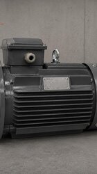
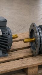
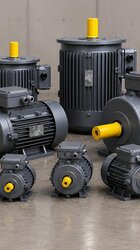
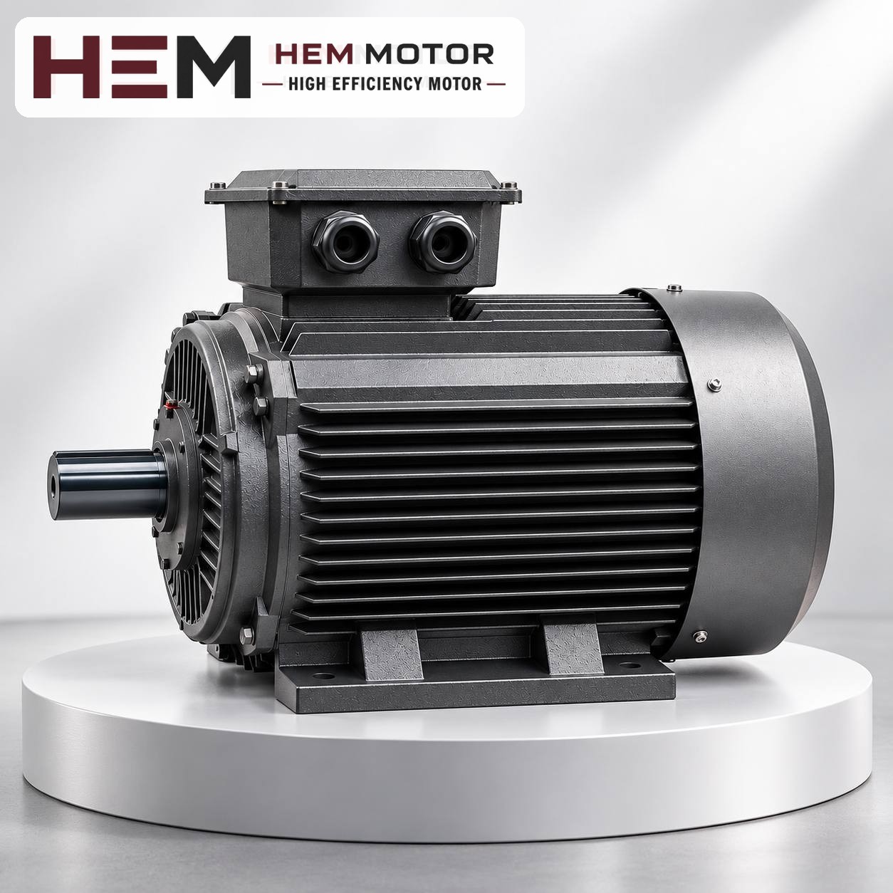

When a foot-mounted motor fails, a motor of the same power but with feet and flange (B35) may be available in stock or from a supplier. The question that comes to mind is simple: can a B35 be fitted in place of a B3? In most cases the answer is yes, but not without a few checks. In this article we look at the difference between B3 and B35, when a B35 fits a foot-mounted installation without problems, in which cases the flange gets in the way, and why the reverse, using a B3 in place of a B35, carries risk.

What is the difference between B3 and B35?
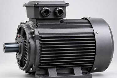
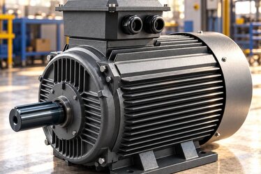
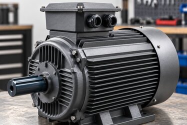
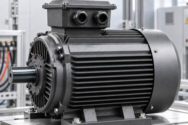
B3 is the horizontal mounting arrangement in which the motor is bolted to a base or baseframe by its feet only. B35 carries the same feet and in addition has a B5-type flange with through holes on the front end shield. In short, B35 = B3 + B5. On motor nameplates these arrangements may also be written with IEC codes: IM 1001 for B3 and IM 2001 for B35 are commonly seen.
The difference between the two arrangements lies not in the frame itself but in the front end shield. For the same IEC frame code (e.g. 100L, 132M), the stator, rotor, electrical values and foot layout are the same; in a B35 only the front end shield is made with a flange. That is why using a B35 motor in a foot-mounted installation is possible in principle: the flange is left free and the motor is fixed by its feet.
Checks to make before replacing
Before fitting a B35 motor in place of a B3, check the points below in order. If all are suitable, the replacement can be made without touching the base.
- Is the frame code the same? The IEC frame code on the old motor's nameplate (e.g. 112M) must be the same as the new motor's. With the same code, the foot hole spacing and shaft height are the same by standard; with a different code, the base needs adapting.
- Is the shaft end the same? Shaft diameter, length and key size must be the same so that the pulley or coupling can be reused. These values depend on the frame and are confirmed from the technical drawings.
- Does the flange project below the base surface? On some frames, the outer diameter of the flange is greater than twice the shaft height. In that case the lower edge of the flange drops below the underside of the feet and the motor cannot sit fully on a flat base. The solution is to position the motor so that the flange stays in front of the base edge, or to cut a clearance for the flange in the base.
- Is there room in front of the flange? The flange forms a projection on the front end shield towards the shaft. If the pulley, coupling, belt guard or machine body is very close to this area, the flange may touch it. Changing the position of the pulley on the shaft should be considered a last resort, since it can increase the load on the bearing.
- Is the terminal box orientation suitable? The box is generally on top of the frame; check that the cable entry suits the existing installation.
Shaft, flange and foot dimensions are not given in this article; they are in the 2026 technical and product catalogue by frame. For a general summary of the mounting options, see the question on mounting arrangements.
Fixing a B35 by both feet and flange
A B35 motor is sometimes fixed both by its feet to a baseframe and by its flange to a gearbox or pump casing. In this arrangement the motor is secured from two separate surfaces. If the foot and flange surfaces are not perfectly aligned with each other, tightening the bolts puts stress on the frame and the bearings. In this type of connection, thin shims are placed under the feet; the flange connection is seated first, and then the feet are tightened without stress.
If you fit a B35 in place of the old B3 motor and fix it by the feet only, this problem does not arise; the flange is not bolted to anything.
The reverse: can a B3 be used in place of a B35?
This direction is much riskier. If the existing motor is connected by its flange to a gearbox, pump or machine body, it means the flange carries part or all of the load and aligns the motor axially. Because a B3 motor has no such flange:
- The axial alignment between the motor and the connected equipment is lost.
- The feet alone have to carry the load; vibration increases.
- Without the flange's spigot, shaft and coupling alignment has to be done by measurement on site.
If the flange is just sitting there like a cover and is not connected to anything, a B3 can also be used. But if the flange really does serve as a connection, the new motor must also be flanged and the flange size must match. The flange size is confirmed with the order; it is not assumed that a flange fits your connection just by looking at the "B5" name.