English
 Français
 Türkçe
 Español
 Русский


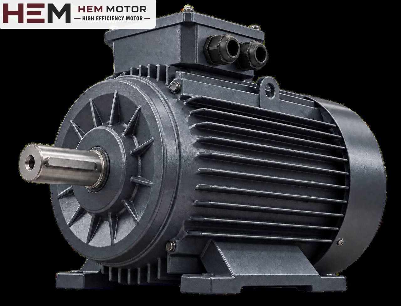

In a concrete batching plant, the screw conveyor under the cement silo carries material to the weighing hopper and may start and stop hundreds of times a day. When its motor fails, most operators first read the power on the nameplate and look for the same kW. Yet in a cement screw the power is not the only value that defines the motor: the inclination of the screw, the input side of the gearbox, the frequent starts caused by the weighing cycle, the dusty and open environment under the silo and the first start from a tube that stayed full overnight must all be considered together. In this article we go step by step through how to match the motor and the gearbox and which information should be collected before a replacement.

A cement screw is not an ordinary conveyor
The screw under the silo takes cement from the conical silo outlet and delivers it to the weighing hopper above. That is why in most plants the screw is not horizontal but installed at a certain angle. As the inclination increases, the flight not only moves the material forward but also lifts it; cement sliding back inside the tube creates additional friction. This is why, of two screws with the same diameter and length, the inclined one needs more drive power. When replacing an old motor there is usually no problem if the angle of the screw has not changed; but if the plant has been relocated, the screw extended or the angle made steeper, the previous nameplate value may no longer be a correct reference.
The cement itself also changes the behaviour. Freshly flowing, aerated cement from the silo flows almost like a liquid; cement that has waited for a long time and compacted forms lumps inside the tube. In humid weather, crusting at the tube inlet can also be seen. When choosing the motor, these two extremes, free flow and compacted fill, need to be considered separately.
Gearbox input flange and the existing motor frame
In most cement screws the motor is flanged directly onto the input side of the gearbox. In this arrangement the mounting interface must match before the motor power does. The gearbox input flange is machined for a specific IEC frame size; the motor shaft diameter, keyway and flange type must fit this input. A large flange with through holes (B5) and a small flange with tapped holes (B14) cannot replace each other.
In practice, the following order is followed:
- Note the IEC frame code (e.g. 132S, 132M, 160M) and the mounting arrangement on the old motor's nameplate.
- Check on the gearbox nameplate or in its catalogue which frame the input side is designed for.
- If you are thinking of changing the motor power, check whether the new power is in the same IEC frame; if the frame gets larger, the flange and shaft may no longer fit.
- Do not exceed the torque limit the gearbox can transmit; a more powerful motor may overload the gearbox.
At HEM Motor, B3, B5, B14, B34, B35 and vertical V1/V3/V5/V6/V15 mounting arrangements are offered according to the frame; the flange size is confirmed with the order. Suitability is not confirmed just by looking at B5 or B14 in a model name. You can compare dimensions in the technical drawings and the product catalogue, and see the mounting arrangements FAQ for the options. General information about motors to be coupled to gearboxes is on the electric motors for gearboxes page.
Weighing cycle: how do frequent starts and stops affect the motor?
A cement screw is not a machine that runs continuously. When the scale approaches the target value the screw stops, and it runs again for the next batch. In some control systems the screw is switched on and off at short intervals in the final part for accurate dosing. At every start the motor draws several times its rated current and the winding heats up. As starts become more frequent, the motor has less time to cool down.
For this reason, the following information is important in a replacement request:
- Roughly how many batches are made per hour and how many times the screw starts and stops in each batch
- Whether short pulse operation is used in the final dosing
- Whether the motor is started direct-on-line, with star-delta, with a soft starter or with a frequency inverter
Star-delta starting reduces the starting current but also reduces the starting torque; on a full, inclined screw this may prevent the motor from starting in the star position. A frequency inverter allows soft starting and speed adjustment. Our three-phase series are suitable for speed control with a frequency inverter; for long operation at low speed with full torque an external fan may be required, and if the cable between drive and motor is long a dv/dt or sine filter is considered; these conditions are stated with the order. Details are on the inverter FAQ page. When the thermal relay trips frequently, the protection setting also needs to be reviewed; for this you can read our motor protection article.
Dust, rain and sun under the silo
The area under the silo is usually open, and the motor is exposed to rain, sun and the temperature difference between day and night. Cement dust also penetrates even the finest gaps. HEM Motor's three-phase models on sale are offered with IP55 protection and class F insulation; still, paying attention to a few points extends the motor's life:
- A layer of cement building up on the cooling fins makes heat dissipation harder; it should be cleaned regularly.
- The front of the fan cover should not be blocked by dust or bag residue.
- On an inclined screw the motor also sits at an angle; where condensate water will collect and the orientation of the terminal box should be discussed with the order.
- In installations exposed to direct rain, a simple canopy or protective cover helps; this cover must not block the cooling air.
As for frame material, a cast iron frame is frequently preferred on plant sites where vibration and impact are heavy. To evaluate it together with the other drives in the plant, you can look at the concrete plant electric motors page.